Method and apparatus for producing a conductivity log unaffected by shoulder effect and dip from data developed by a well tool

a technology of conductivity log and data, applied in the field of well logging, can solve the problems of affecting the quantitative formation evaluation of conventional techniques, affecting the practicality of evaluating the conductivity of formations, and corrupting the measuremen

Inactive Publication Date: 2001-04-10
SCHLUMBERGER TECH CORP
View PDF12 Cites 23 Cited by
  • Summary
  • Abstract
  • Description
  • Claims
  • Application Information

AI Technical Summary

Benefits of technology

U.S. Pat. No. 5,041,975 describes a method for correcting data developed by the well tool of the '605 patent, to eliminate the effects of the borehole on the measured data. U.S. Pat. No. 5,184,079 describes a method for correcting logs, developed from a logging tool, disposed in a wellbore at a dip angle relative to the formation layers, to eliminate the effects of the dip angle on the resistivity logs. The applicability of this correction method is limited to dip angles less than about 45 degrees. Another method for correcting induction logs with high apparent dip angle effects was described by Barber et al., Interpretation of Multiarray Induction Logs in Invaded Formations at High Relative Dip Angles, SPWLA THIRTY-NINTH ANNUAL LOGGING SYMPOSIUM, June, 1998. This method requires time-consuming model calculations, making it less desirable for operations at the well site while logging. An underlying criterion of the methods described by the '079 patent and Barber et al. is the requirement that the dip angle be known before the methods can be applied.

Problems solved by technology
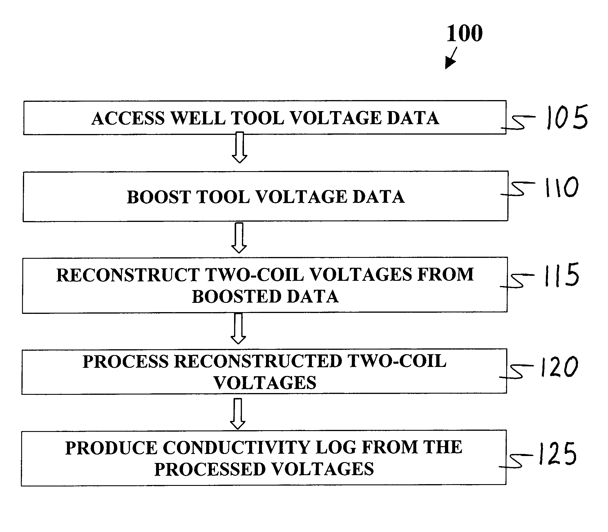
Conventional techniques for evaluating the conductivity of formations have practical limitations.
Neighboring layers in high-contrast (in terms of resistivity) thin-layer formations can corrupt the measurement results--known as shoulder effect.
The TM horns observed are useful to detect layer boundaries, but are detrimental for quantitative formation evaluation.
The applicability of this correction method is limited to dip angles less than about 45 degrees.
This method requires time-consuming model calculations, making it less desirable for operations at the well site while logging.

Method used


Image

  • Method and apparatus for producing a conductivity log unaffected by shoulder effect and dip from data developed by a well tool
  • Method and apparatus for producing a conductivity log unaffected by shoulder effect and dip from data developed by a well tool
  • Method and apparatus for producing a conductivity log unaffected by shoulder effect and dip from data developed by a well tool

Examples


Embodiment Construction

In the interest of clarity, not all features of actual implementation are described in this specification. It will be appreciated that although the development of any such actual implementation might be complex and time-consuming, it would nevertheless be a routine undertaking for those of ordinary skill in the art having the benefit of this disclosure.

Overview of the Problem

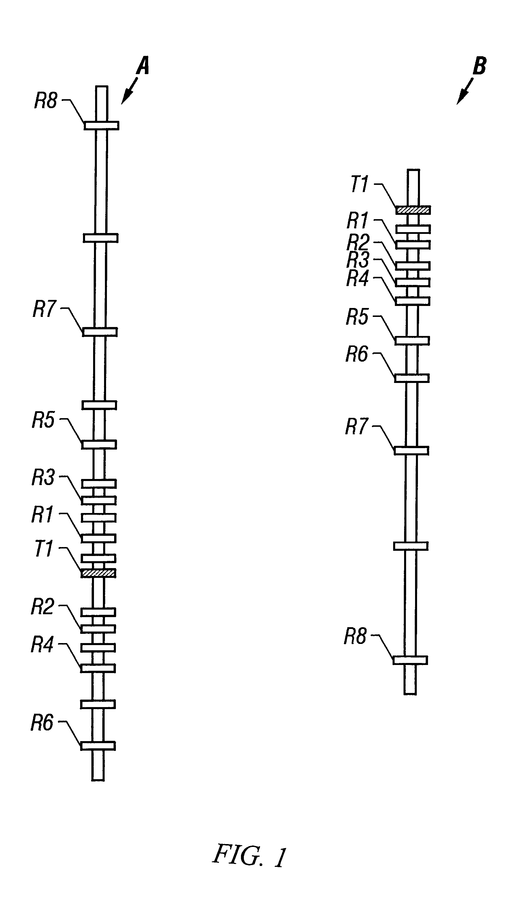
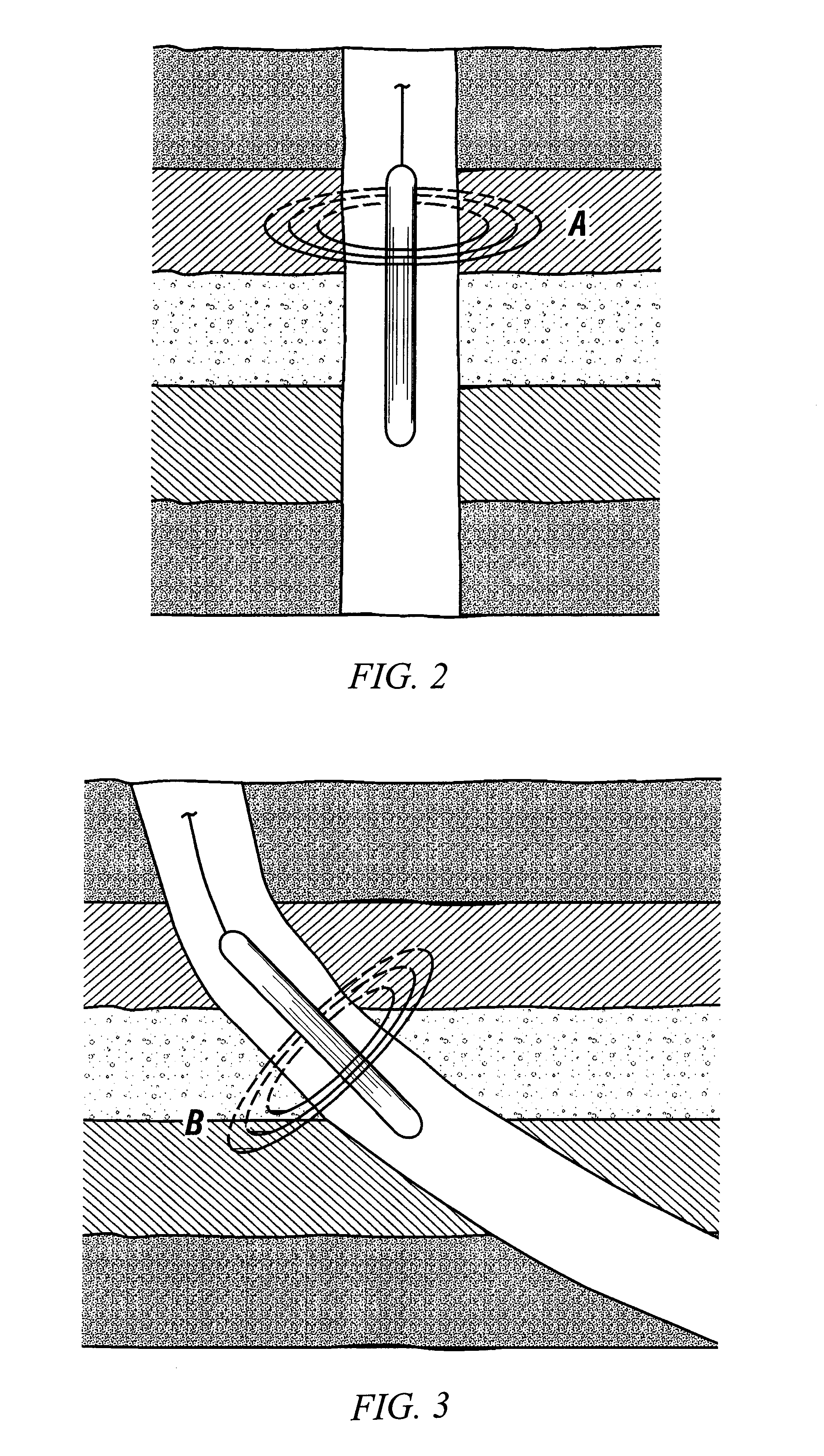
FIG. 1 shows the coil layouts of two induction array well tool designs A, B (disclosed in the '605 patent) which may be used to implement the present invention. Each design includes a transmitter T1 and a plurality of receiver pairs Rn (n>0). As discussed above, energy transmitted into a formation propagates in the formation and is detected by a receiver pair Rn as a complex-valued phasor voltage (not shown). Several processing steps are applied to the receiver voltage data to obtain estimates of the formation conductivity as described by J. F. Hunka et al., A New Resistivity Measurement System for Deep Formatio...


PUM


Abstract

A method and apparatus for producing a conductivity log, unaffected by shoulder effect and dip, from voltage data developed by a well tool disposed in a borehole. The method involves accessing the voltage data developed by the tool, processing the data, reconstructing two-coil voltage data, and computing differences of the two-coil data, to derive a conductivity profile representative of the formation. The apparatus forms part of a well logging system including a well tool adapted to be moveable through a borehole. The apparatus being coupled to the well tool and adapted with means to access voltage data developed by the receivers disposed on the well tool. The apparatus further adapted with means for boosting the voltage data, means for reconstructing two-coil voltages from the boosted voltage data, means for processing the reconstructed two-coil voltage data, and means for producing a conductivity log from the processed two-coil voltages.

Description

1. Field of the InventionThis invention relates to the field of well logging and, more particularly, to well logging methods and apparatus for determining formation properties, such as conductivity, in high-contrast thin-layer formations or at high dip angles, with greater accuracy than prior methods. Still more particularly, this invention relates to an improved method for processing multiple voltage data obtained during logging with an induction array well tool and creating a depth tagged representation of resistivity or conductivity from a formulated difference of the voltage data. The invention has general application in the well logging art, but is particularly useful at a well site while logging.2. Description of Related ArtInduction logging is a well-known form of electromagnetic logging used to make a determination of the conductivity (or its inverse, resistivity) profile of the earth formations surrounding a borehole. U.S. Pat. Nos. 3,340,464; 3,147,429; 3,179,879; 3,056,91...

Claims


Application Information

Patent Timeline
Patent Type & Authority Patents(United States)
IPC IPC(8): G01V3/28G01V3/38G01V3/18
CPCG01V3/28G01V3/38
Inventor MINERBO, GERALD N.
Owner SCHLUMBERGER TECH CORP
Why Eureka
Try Eureka