Radiocommunication device and a dual-frequency microstrip antenna

a radiocommunication device and microstrip technology, applied in the direction of antennas, antenna details, antenna earthings, etc., can solve the problems of complex implementation, unfavorable transmission, and unwanted standing wave in the lin

Inactive Publication Date: 2001-04-17
WSOU INVESTMENTS LLC
View PDF6 Cites 47 Cited by
  • Summary
  • Abstract
  • Description
  • Claims
  • Application Information

AI Technical Summary

Benefits of technology

enabling simple implementation of a dual frequency antenna, more particularly an antenna for which the ratio is in the range approximately 0.2 to approximately 0.8 and in particular around 0.5, by choosing more freely than previously the ratio between two wanted resonant frequencies of the antenna,
giving the antenna a sufficiently wide bandwidth around each of the two resonant frequencies for a transmit frequency and a receive frequency to be situated within that bandwidth without crosstalk occurring,
enabling easy and accurate adjustment of the two resonant frequencies,
enabling use of a single coupling device whose impedance can easily be matched for each of the two resonant frequencies, and
Whatever the nature of the antenna coupling device used to enable the radiocommunication device to operate in two frequency bands centered respectively on the quarter-wave and on the half-wave resonant frequencies, the invention is advantageous if the ratio between the required two operating frequencies takes certain values, and more particularly if the ratio is in the range approximately 0.2 to approximately 0.8, in particular around 0.5. The advantage is that it enables the required ratio to be obtained relatively simply and efficiently by the combined use of two resonance modes, one of the quarter-wave type and the other of the half-wave type, established from traveling waves traveling across the same area in two crossing directions.

Problems solved by technology

Transfer is generally imperfect, i.e. the coupling device reflects some of the energy towards the connection line, which causes an unwanted standing wave in the line.
Its implementation is complicated by the need to provide impedance converter means.
It is difficult to adjust the resonant frequencies accurately to required values.
Incorporating localized short-circuits complicates the implementation of the antenna.
The difference between the two resonant frequencies is too small in some applications.
The need to use a matching system complicates the implementation of the antenna.

Method used


Image

  • Radiocommunication device and a dual-frequency microstrip antenna
  • Radiocommunication device and a dual-frequency microstrip antenna
  • Radiocommunication device and a dual-frequency microstrip antenna

Examples


Embodiment Construction

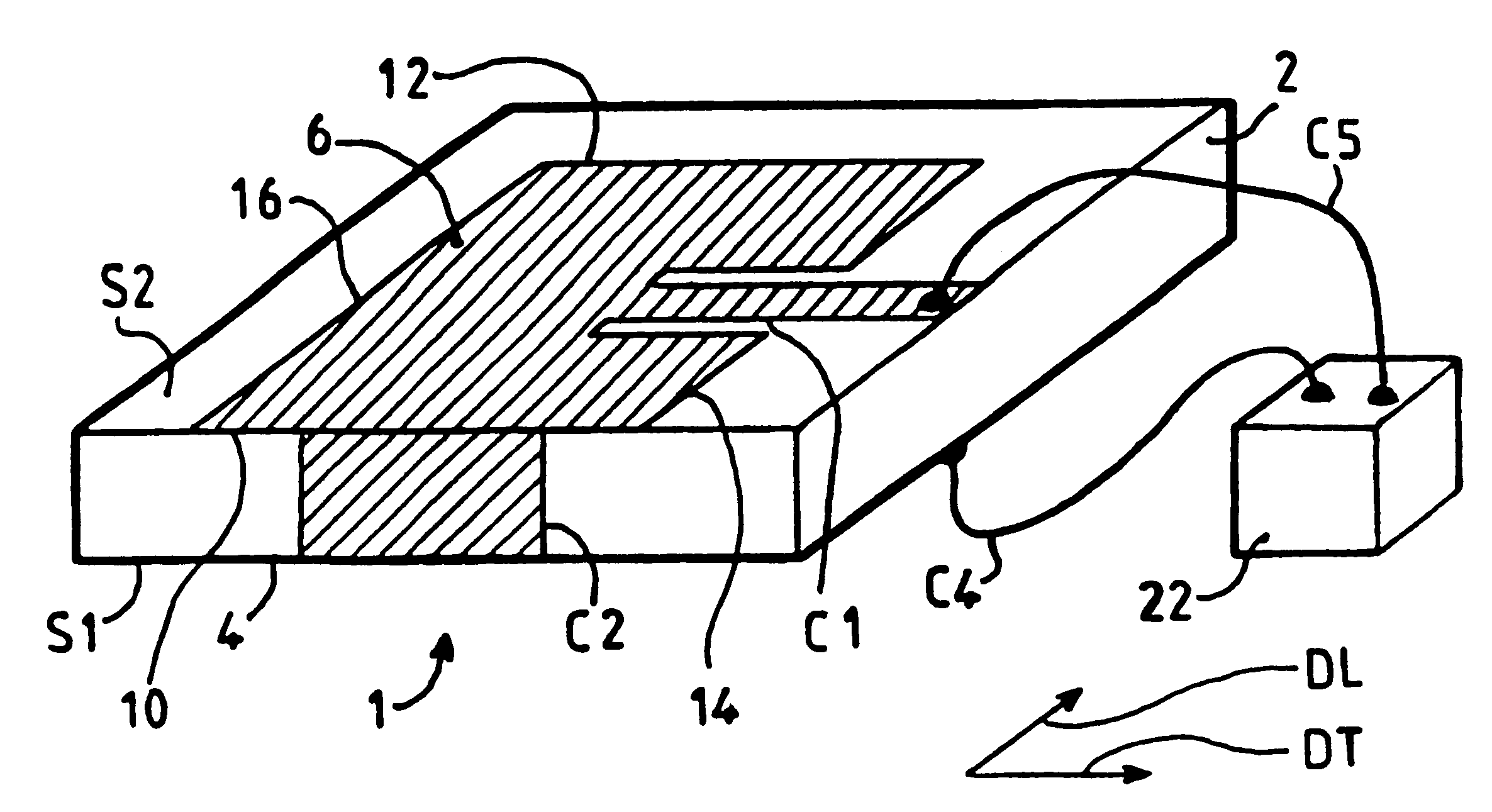
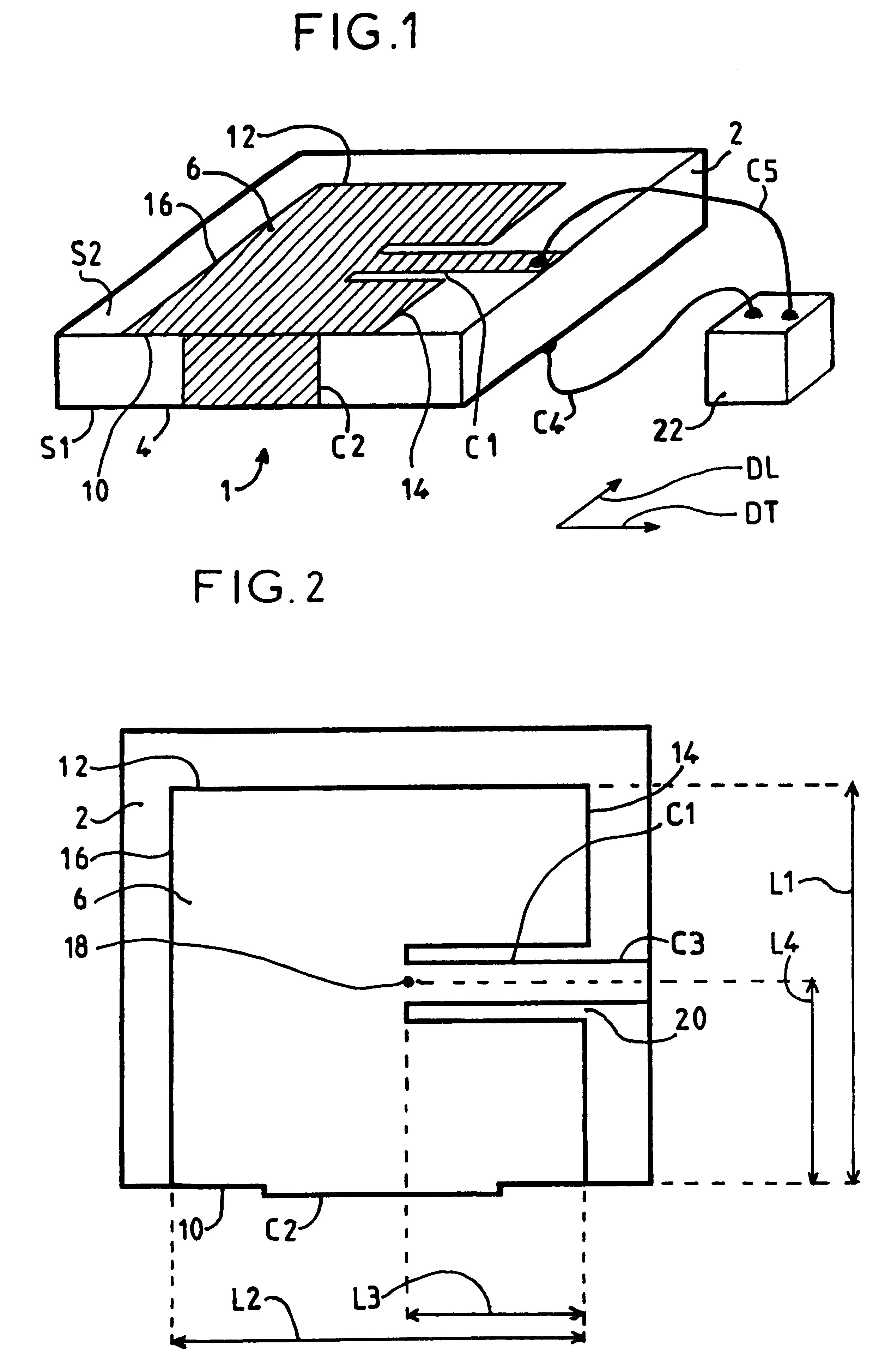
As shown in FIGS. 1 and 2, and in a manner that is known per se, an antenna in accordance with the present invention includes a resonant structure including the following components:

A dielectric substrate 2 having two opposite main surfaces extending in directions defined in the antenna and constituting horizontal directions DL and DT, which directions may depend on the area concerned of the antenna. The substrate can have various shapes, as previously explained. Its two main surfaces are a bottom surface S1 and a top surface S2.

A bottom conductive layer extending over all of the bottom surface, for example, and constituting a ground 4 of the antenna.

A top conductive layer extending over an area of the top surface over the ground 4 to constitute a patch 6. The patch has a length and a width in said two horizontal directions that are defined hereinafter and which constitute a longitudinal direction DL and a transverse direction DT, respectively, and its periphery can be considered as...


PUM


Abstract

An antenna has a patch with a rear edge provided with a short circuit enabling a quarter-wave resonance to be established. A half-wave resonance can also be established between two lateral edges of the patch. The same coupling device couples the antenna to a transmitter or receiver for each of the two resonant frequencies. It includes a coupling strip penetrating the patch between the edges of a slot extending from one lateral edge. The antenna is particularly applicable in dual mode mobile telephone system using GSM and DCS standards.

Description

The present invention is generally concerned with radiocommunication devices, in particular mobile telephones, and it is more particularly concerned with microstrip antennas for use in such devices. An antenna of this kind is known as a "microstrip patch antenna" and includes a patch which is typically formed by etching a metallic layer.The microstrip technique is a planar technique used to produce lines conveying signals and antennas coupling such lines and radiated waves. It uses conductive strips and / or patches formed on the top surface of a thin dielectric substrate separating them from a conductive layer on the bottom surface of the substrate and constituting a ground for the line or antenna. A patch is typically wider than a strip and its shape and dimensions are important features of the antenna. The substrate is typically a plane rectangular sheet of constant thickness and the patch is also typically rectangular. This is not obligatory, however. In particular, varying the th...

Claims


Application Information

Patent Timeline
Patent Type & Authority Patents(United States)
IPC IPC(8): H01Q5/00H01Q9/04H01Q1/38H01Q13/08H01Q5/10H01Q5/364
CPCH01Q9/0421H01Q5/364H01Q9/0442
Inventor GRANGEAT, CHRISTOPHEHERVE, PASCALLORCY, LAURENCEKOUAM, CHARLES NGOUNOU
Owner WSOU INVESTMENTS LLC
Why Eureka
Try Eureka