Dynamo-electric machines and control and operating system for the same

a technology of dynamo-electric machines and operating systems, which is applied in the direction of electronic commutators, motor/generator/converter stoppers, dynamo-electric converter control, etc., can solve the problems of affecting the operation of the commutator, causing disastrous sparking at the brush contact, and wearing at the receding edges of the commutator segments and at the trailing brush tips

Inactive Publication Date: 2001-04-24
GRUND MOTORWERKS
View PDF16 Cites 30 Cited by
  • Summary
  • Abstract
  • Description
  • Claims
  • Application Information

AI Technical Summary

Problems solved by technology

This "short-circuited current", as it is called, can under some circumstances produce disastrous sparking at the brush contact.
If the commutation is not properly accomplished, this results in a high voltage spike, which can cause sparking.
The effect of sparking is to cause wearing at the receding edges of the commutator segments and at the trailing brush tips.
Another method is to use commutating poles, which makes brush shifting unnecessary, since the proper commutating flux is brought to the short-circuited coil.
a. The shunt motor has a fair starting torque and has relatively less variations in speed for changes in loads. It is used where the load requires a more constant speed and the starting torque demanded is not excessive.
b. The series motor operates through a wide range of speed as the load changes. In very light loads the motor is likely to "run away". It gives very great starting torque and is therefore used where a heavy starting torque is demanded, and where the motor may be positively connected to its load.
c. The compound motor has characteristics between those of a shunt and a series motor and hence has a starting torque greater than that of the shunt motor, but less than that of the series motor. In FIG. 6, which is derived from the figure of page 326 of Hehr and Harness book, the speed and torque characteristics of the three types of motor are shown, where the torque values are along the vertical axis, and current is along the horizontal axis.
Thus, if the current reaches too high a level, it will burn out the motor.
However, since the rotational speed is very slow, and since power output equals force times distance, even though the torque is very high, the effective work done is rather low.
However, the wasted energy is extraordinarily high and this is being dissipated in rheostat.
Further there are practical constraints on the design of electric motors such as a maximum voltage levels imposed by certain design constraints, etc.

Method used


Image

  • Dynamo-electric machines and control and operating system for the same
  • Dynamo-electric machines and control and operating system for the same
  • Dynamo-electric machines and control and operating system for the same

Examples


second embodiment

The switching arrangement of the present invention is disclosed in FIG. 17. Since there is an even number of inductive armature coils, there will be more than one coil segment which is being switched at a given time. The voltage spike for each of these coil segments will be opposite to one another. These two voltage spikes can thus be directed simultaneously into the power buses so that these effectively would balance each other without power loss.

In FIG. 17 there are shown eight separate switches designated A through G. There are eight coils, and each of the numbers 1 through 16 represent individual coil segments. The coil segments are disposed diametrically opposite to one another. Thus, the segments 1 and 9 make up one coil, the segments 2-10 make up another coil segment, etc.

To describe the operation of the arrangement shown in FIG. 17, at any one time one of switch assemblies (such as shown at 92 in the prior embodiment) has the positive switch made conductive, while an opposit...

third embodiment

FIG. 18 shows the present invention, where the a stator of the motor 60a comprising two north poles and two south poles, and there are eighteen coils. The switching between the coils is accomplished in generally the same manner as illustrated in FIG. 17. The embodiment of FIG. 18 is shown to illustrate that the present invention can be embodied in a motor where there are multiple north and south poles.

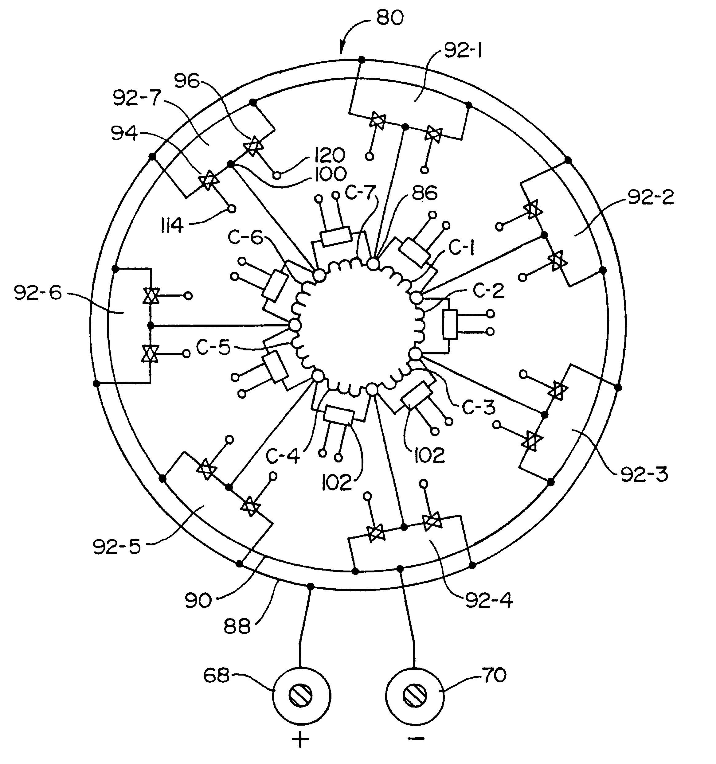
FIG. 19 shows a fourth embodiment of the present invention. In this embodiment, there are six coils designated C-1b through C-6b. As in the first embodiment, there are switch assemblies 92, each having positive and negative switches 94 and 95. However, the individual coils C-1b through C-6b are not connected to one another in series. Rather, each end of each coil are connected to an individually related switch assembly 92.

Thus, in the operation of the embodiment of FIG. 19, each coil is made conductive by turning on the positive switch 94 of one of its related switch assemblies, and at...

fifth embodiment

FIG. 20 shows the present invention where the concept of the present invention is adapted to a design related to a synchronous motor. In a synchronous motor, the flux field is developed through an AC current so that the flux field travels a circumferential path around the stationary outer member (the "stator). In a conventional synchronous motor, the rotor positioned within the stator often simply has permanent magnets with the poles of the magnet being positioned adjacent to the rotating flux field so that the rotational movement of the flux field interacts with the poles of the rotor poles to cause the rotor to rotate synchronously with the field traveling around the circumference of the stator.

To incorporate the present invention in the basic design of a synchronous motor, the rotor, instead of being provided as permanent magnets, is provided with an armature made in accordance with the present invention having the switching and control assembly of the present invention. The swit...


PUM


Abstract

A dynamo-electric machine which can function as a motor or a generator. The machine comprising a stator and an armature, and switching of the armature coils is accomplished by means of a switching control assembly which is mounted to, and rotates with, the armature. In operation as a motor, direct current is supplied through brushes to slip rings that rotate with the armature, and the DC current supplied is first passed through switch means in the control assembly to deliver the current in properly timed relationship with respect to the rotation of the rotor. This provides greater versatility in the operation of the motor/generator and eliminates many of the problems related to the use of conventional brush commutation commonly used in present day DC motors and generators.

Description

a) Field of the InventionThe present invention relates generally to electrical machines (which include both motors and generators), and more particularly to a system (apparatus and method) for providing power to the machine components and a control and operating system for the same. More particularly, this relates to such a machine and system which does not use brush commutation, and which provides optimized performance of the machine, and also enables the overall design of the machine itself to be improved for better performance.One of the more common electrical machines used for various industrial applications is the conventional commutator controlled DC motor having a stator with at least one set (pair) of oppositely positioned fixed north and south poles, and a rotor positioned between the poles. The rotor is wound with coils that extend parallel to the axis of rotation of the rotor and are positioned at circumferentially spaced locations around the rotor.Electric power is suppl...

Claims


Application Information

Patent Timeline
Patent Type & Authority Patents(United States)
IPC IPC(8): H02K29/06H02K29/00H02K23/02H02K23/00H02K21/28H02K23/04H02K21/00H02P23/00
CPCH02K29/06H02K21/28H02K23/00H02K23/04
Inventor BLUM, DIETER W.
Owner GRUND MOTORWERKS
Why Eureka
Try Eureka