
Method and apparatus for reducing iron-oxides-particles having a broad range of sizes

a technology of iron oxides and particle reduction, applied in shaft furnaces, metal processing, furnaces, etc., can solve the problems of process not teaching the use of moving bed reactors, loss of products, pollution disposal,

Inactive Publication Date: 2001-05-01
HYLSA SA DE CV
View PDF20 Cites 15 Cited by
  • Summary
  • Abstract
  • Description
  • Claims
  • Application Information

AI Technical Summary

Benefits of technology

It has long been desired to have a direct reduction process wherein an iron ore charge with both coarse and fine particles could be processed in one single reactor shaft continuously to achieve high metallization rates with little loss of efficiency as is possible with separate processing of either one alone.
It is therefore an object of the present invention to provide a basically moving bed method and apparatus yet having the extended capability to reduce effectively and efficiently iron oxide particles having a broad range of sizes, including substantial amounts of fines (or the flexibility to handle any sub-range therein) in a single reduction reactor, particularly to a high degree of metallization.
It is a further object of the present invention to provide method and apparatus for handling in a moving bed reactor pellets and lumps that can have in addition a large percentage of fines without requiring a proportionately large increase in capital equipment for handling such additional fines (and yet is capable even of effectively processing fines exclusively).
It is a yet another object of the present invention to provide method and apparatus optionally capable of handling lumps, ore concentrates, and fines in a single reactor without the need for minimizing the fines present by means of pelletizing or sintering, thus eliminating the cost of such latter steps that are typical in the prior art in the overall production of DRI.

Problems solved by technology

It is well known to those skilled in the art that fines cause several problems when introduced into or produced in a moving bed reactor.
This U.S. Pat. No. 5,435,831 discloses that if fines are introduced directly to the shaft reduction furnace, the fines would be blown out into the scrubber for separation from the gas stream (and thus not only be lost as a product but also become a pollution disposal problem).
This process does not teach use of a moving bed reactor.
However, this should not be done if the profile of the upper surface of the moving bed of coarse particles so lopsided as to result in unacceptably uneven reduction of the particles.

Method used


Image

  • Method and apparatus for reducing iron-oxides-particles having a broad range of sizes
  • Method and apparatus for reducing iron-oxides-particles having a broad range of sizes
  • Method and apparatus for reducing iron-oxides-particles having a broad range of sizes

Examples


examples

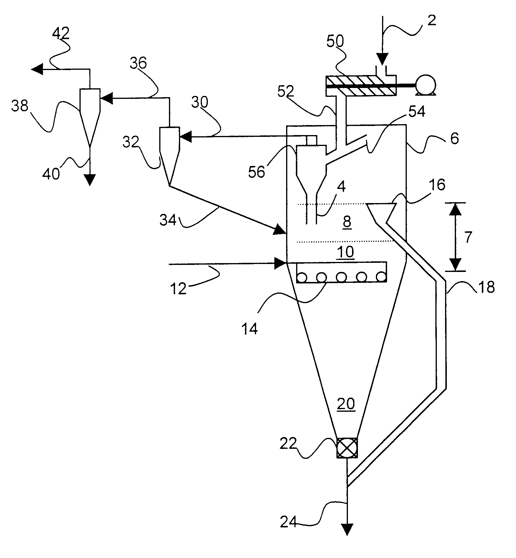
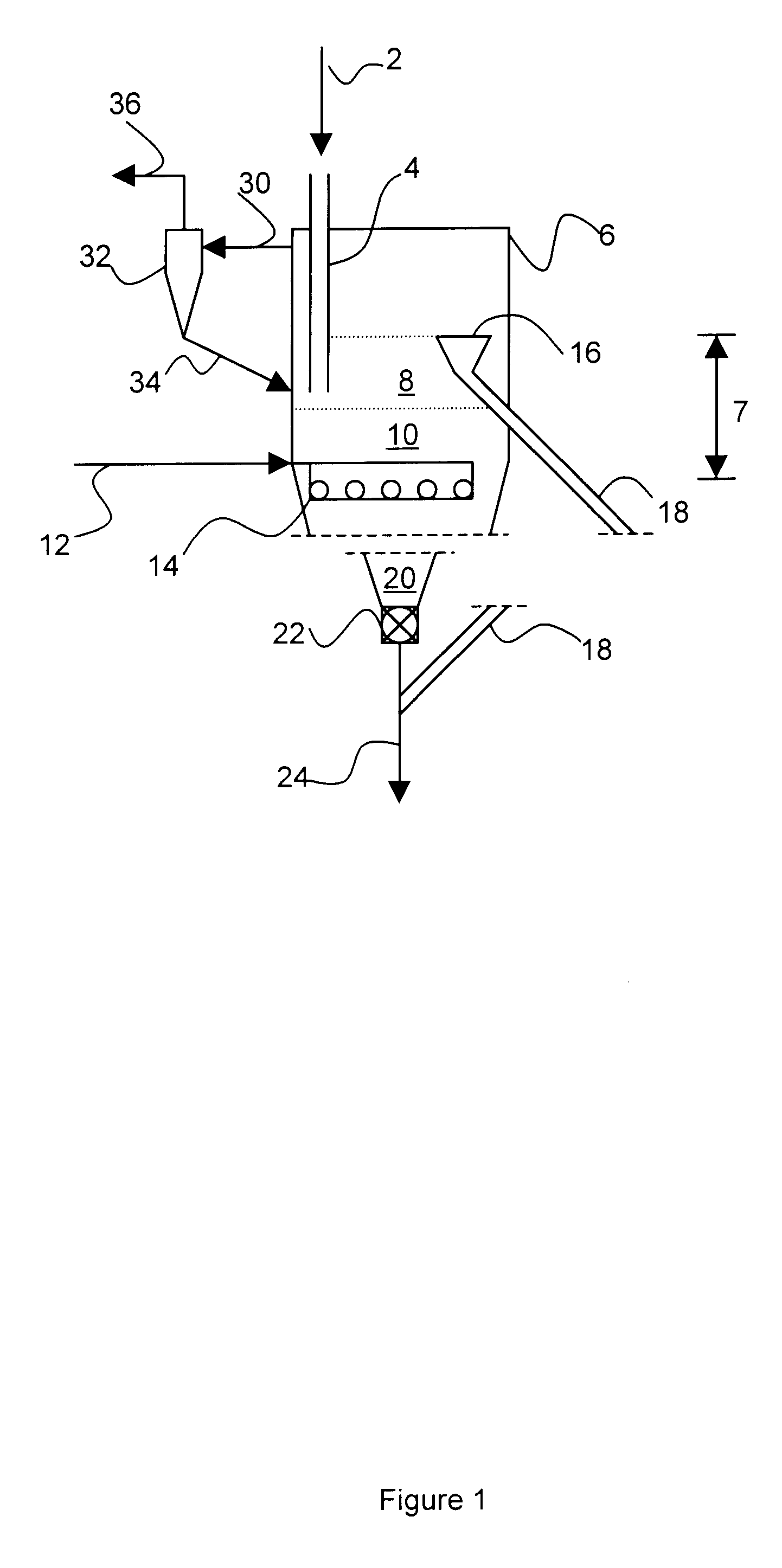
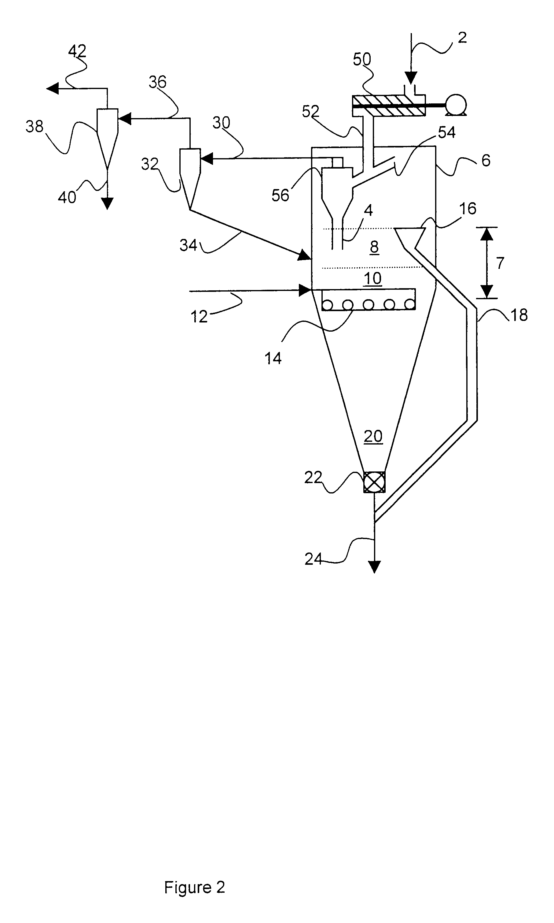
In pilot plant tests of structure most like FIG. 1, the following results were obtained:

From this table, it can be seen that the percentage of fines available for the fluidized bed is 31.1712 (in the 0.00-0.841 size range) for test C1, and 31.4338 for test C2. A velocity of 0.6 m / s were needed to suspend 0.5 mm particles and 3.8 m / s to blow this size out of the reactor (while a velocity of 2.8 m / s suspended 5.0 mm particles and 12 m / s to blow these away). From the foregoing table the calculated estimated distribution of particles for test C2 would be 21.7% for 0.00-0.50 mm and 78.3% for 0.50-5.00 mm.

The following is typical of the reducing gas used during the pilot plant testing:


PUM

PropertyMeasurementUnit
Temperatureaaaaaaaaaa
Lengthaaaaaaaaaa

Abstract

Methods and apparatus for the reduction into metallic iron of iron-oxides-containing particles having a broad range of sizes. Particles, typically within a broad range of sizes of about 0.1 mm to about 50 mm, are reduced by contact with a hot reducing gas, preferably from a horizontal gas distributor which defines the bottom of the reduction zone by supplying a uniform upflow of gas mainly composed of hydrogen (and / or carbon monoxide) within a temperature range of 650° C. to 1050° C. and at a velocity of about 0.5-0.7 m / s to fluidize at least some of the particles of a size of about 1.0 mm or less (when present). The reducing gas flows upwardly through a descending moving bed of coarser particles and forms thereabove a fluidized bed of fines, all in a single chamber in a reduction reactor, where the particles charged to the reactor are fed into the fluidized bed, preferably at the lower portion thereof at or near the interface with the moving bed, and the lighter reduced fluidized fines are withdrawn from the reactor from the upper portion of the fluidized bed. The spent reducing gas from the reactor passes through at least one cyclone separator with the fines entrained therein being normally returned to the reactor or optionally being subjected to a lower velocity fluidization in a separate reduction chamber of the reactor.

Description

The present invention describes a method and apparatus for the production of reduced iron ore, sponge iron (more commonly now referred to as Direct Reduced Iron or merely DRI), or the like, in an ironmaking plant wherein the charge of iron-oxide-containing particles fed to the reduction reactor can be in a form at least inclusive of fines. The invention in a preferred aspect particularly provides process and apparatus which has the ability to produce DRI, utilizing iron ore particles having a broad range of sizes (or the flexibility to handle any sub-range therein) without the necessity of prior screening, separate processing, and / or excessive equipment with poor performance typical of prior art attempts to handle both normal size pellets or lumps together with significant amounts of fines (which were subject to uneven reduction, loss of product fines, need for excessive capital structures or the like). These new methods and apparatus according to the present invention are particula...

Claims


Application Information

Patent Timeline
IPC IPC(8): C22B5/14C22B5/00C21B13/00
CPCC21B13/002C21B13/0033C22B5/14C21B2100/22C21B2100/44C21B2100/66Y02P10/134
Inventor VILLARREAL-TREVINO, JUAN A.
Owner HYLSA SA DE CV
Learn More