
Solder alloy

a technology of alloys and alloys, applied in the field of alloys, can solve the problems of mechanical damage of electrodes, insufficient thermal shock resistance, phase production,

Inactive Publication Date: 2001-05-08
MURATA MFG CO LTD
View PDF2 Cites 17 Cited by
  • Summary
  • Abstract
  • Description
  • Claims
  • Application Information

AI Technical Summary

Benefits of technology

The above described solder alloy has a comparatively low Young's modulus and sufficient tensile characteristics. Therefore, it is hard to cause peeling from the bonded electrode, etc., even though a heat stress is present. Also, a solder which has an excellent solderbility to metal phases such as Cu and Ni can be provided. Therefore, a solder alloy excellent in thermal shock resistance can be provided.
The above described solder alloy may be used for soldering the inside of an electronic component.
When using the above described solder alloy as internal solder of an electronic component, even though the heat stress is present at the time of the soldering in mounting the electronic component on a printed circuit board, etc., re-melting and electrode peeling hardly occur and cracks in the bonded internal solder can also be prevented reliably.

Problems solved by technology

Therefore, it is strongly required that the internal solder be difficult to melt by heat stress at the time of mounting electronic-component and be characterized by being difficult to cause cracks, etc.
However, the above described internal solders have a problem in that the thermal shock resistance is not sufficient.
However, there is the problem that a correlation crack is produced between the alpha-phase and the beta-phase or that a crack in the alpha-phase is produced.
Therefore, when a heat stress is imposed, the solder easily mechanically damages the electrodes, and easily causes electrode peeling, etc.
When a heat stress is imposed, it is difficult to cause a crack.
Also, it is hard to mechanically damage bonded electrodes.

Method used


Image

  • Solder alloy
  • Solder alloy
  • Solder alloy

Examples


Embodiment Construction

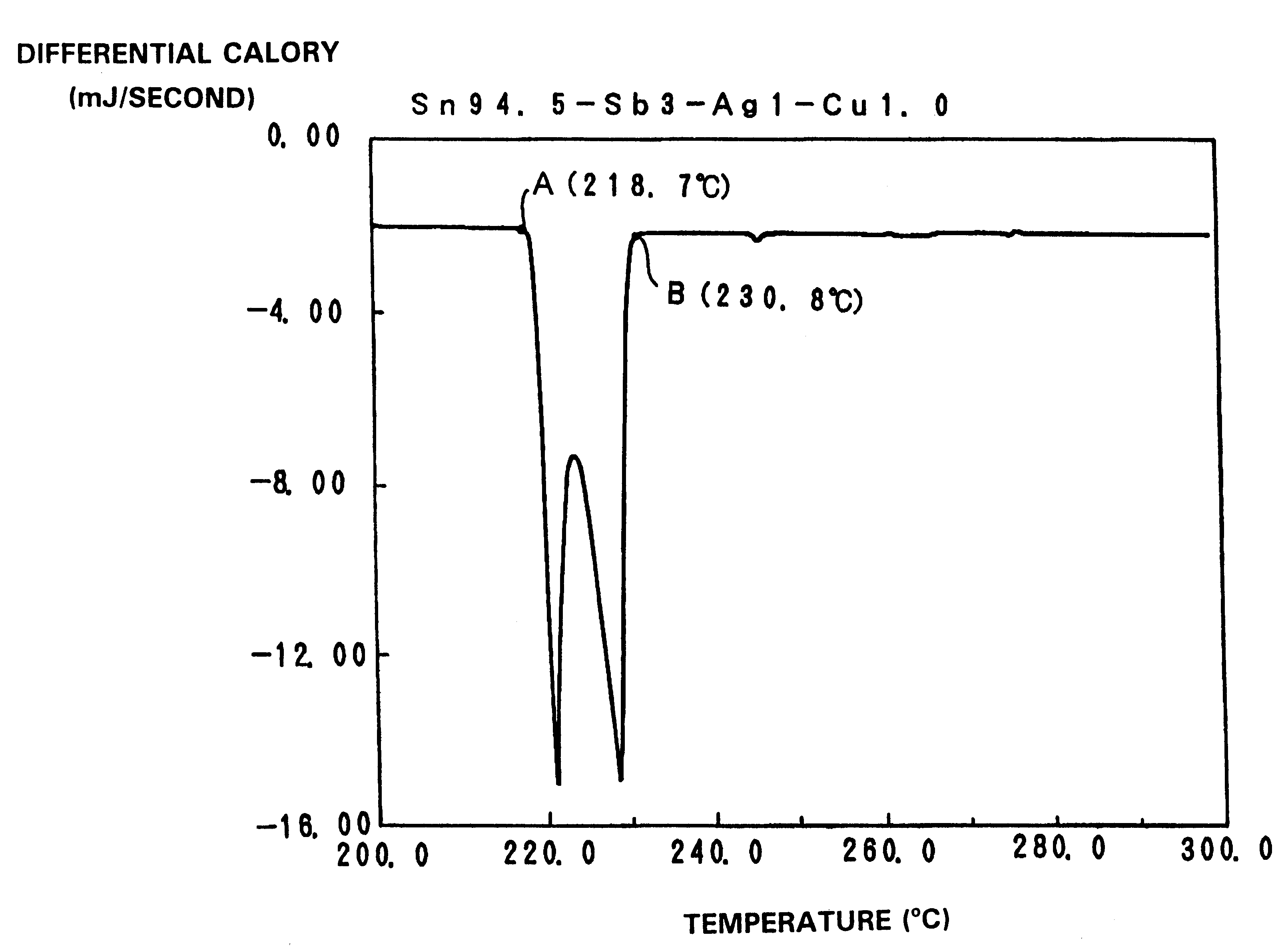
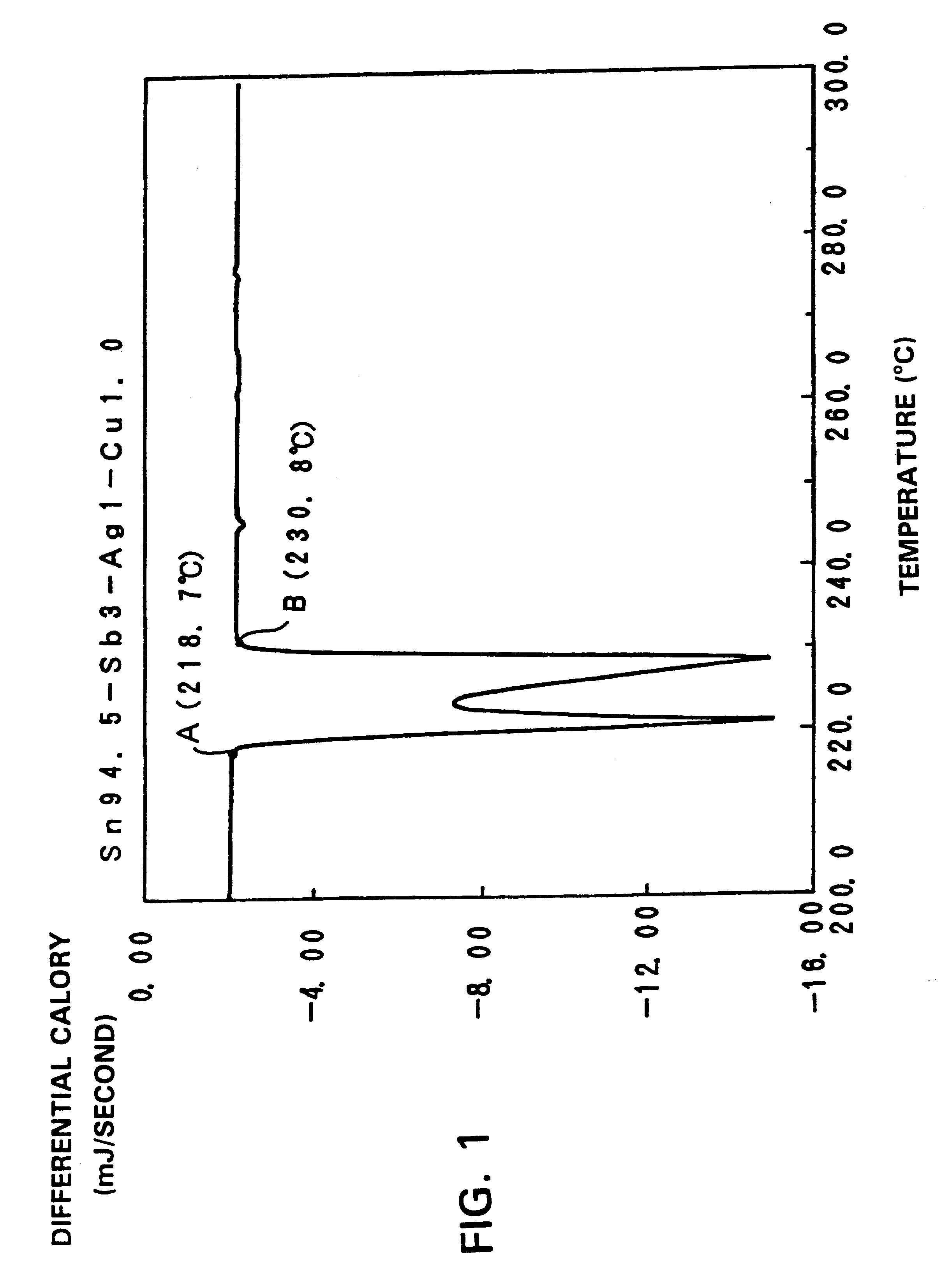
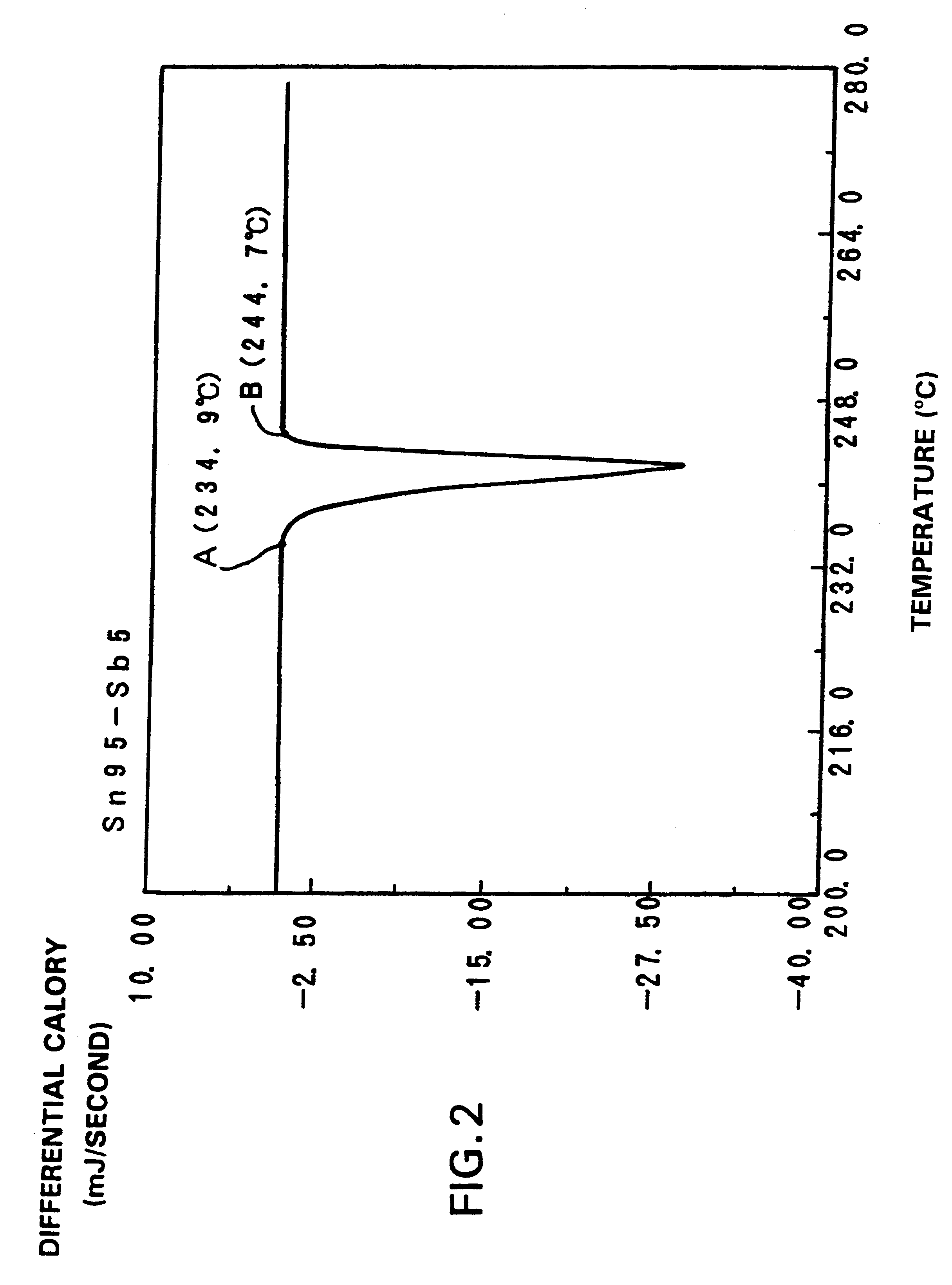
The inventors have tried various modifications of the composition of the Sn--Sb system solder alloy in which the above-mentioned crack is seldom encountered and examined the results zealously.

Generally, Sn system solder alloy has a high Young's modulus and it is easy to cause diffusion to an electrode, etc. Therefore, it is known that it will be easy to cause peeling from an electrode.

The inventors produced the various Sn system solder alloy shown in the following Table 1, based on a Sn--Sb system solder alloy. The various Sn system solder alloys have been tried to make a stable Sn compound which decreases the diffusion to an electrode and eases the stress to an electrode to some extent.

It is noted that sample number 1 in Table 1 consists only of Sn. In a sample number 2, "Sn--Cu0.75" means that Cu is included in an amount of 0.75 wt %, and the remainder consists of Sn. Similarly, in the following sample numbers 3-16, the numeric characters written after chemical element symbols sha...


PUM

PropertyMeasurementUnit
Angleaaaaaaaaaa
Temperatureaaaaaaaaaa

Abstract

The invention provides a solder alloy of Sn, Sb, Ag and Cu, wherein the Sb is about 1.0-3.0 wt %; the Ag is about 1.0 wt % or more and about 2.0 wt % or less; the Cu is about 1.0 wt % or less; and the remainder is Sn. The solder alloy has a comparatively low Young's modulus and sufficient tensile characteristics. Therefore, it resists peeling from the bonded electrode, etc., even though a heat stress is added. Also, a solder which has an excellent solderbility to metal phases such as Cu and Ni can be provided. Therefore, a solder alloy excellent in thermal shock resistance can be provided. The solder alloy may be used for soldering the inside of an electronic component.

Description

1. Field of the InventionThis invention relates to a solder alloy suitable for bonding a terminal etc., for example, in an inside of an electronic component, and, more particularly, relates to a solder alloy having excellent thermal shock resistance.2. Related Art of the InventionConventionally, a structure which contains a piezoelectric resonator in a package which does not obstruct oscillation of a piezoelectric resonator has been widely used in piezoelectric resonance components, etc. In these types of piezoelectric resonance components, the piezoelectric resonator and an electrode and a terminal, etc. which are disposed on the package are bonded with solder.In the solder for bonding to the inside of an electronic component, i.e., a so-called internal solder, heat stress resistance at the time of the soldering for mounting an electronic component in a printed circuit board etc. is required. Therefore, it is strongly required that the internal solder be difficult to melt by heat s...

Claims


Application Information

Patent Timeline
IPC IPC(8): B23K35/26C22C13/00C22C13/02H05K3/34
CPCB23K35/262C22C13/00C22C13/02B23K2201/36B23K2101/36
Inventor KUSABIRAKI, SHIGEMASASUMITA, MANABU
Owner MURATA MFG CO LTD
Learn More