Electrosurgical catheter apparatus and method

a technology of electrosurgical catheters and catheters, applied in the field of electrosurgical catheters, can solve the problems of reducing electrode strength and integrity, and difficult to achieve a low-profile state for insertion

Inactive Publication Date: 2001-05-15
APPL MEDICAL RESOURCES CORP
View PDF6 Cites 79 Cited by
  • Summary
  • Abstract
  • Description
  • Claims
  • Application Information

AI Technical Summary

Problems solved by technology

Although it has always been of interest to increase the current density associated with the wire electrode, this has been difficult to achieve as smaller wire sizes necessarily result in reduced electrode strength and integrity.
Materials forming non-distensible balloons have been preferred, but have made it difficult to achieve a low-profile state for insertion.

Method used


Image

  • Electrosurgical catheter apparatus and method
  • Electrosurgical catheter apparatus and method
  • Electrosurgical catheter apparatus and method

Examples


Embodiment Construction

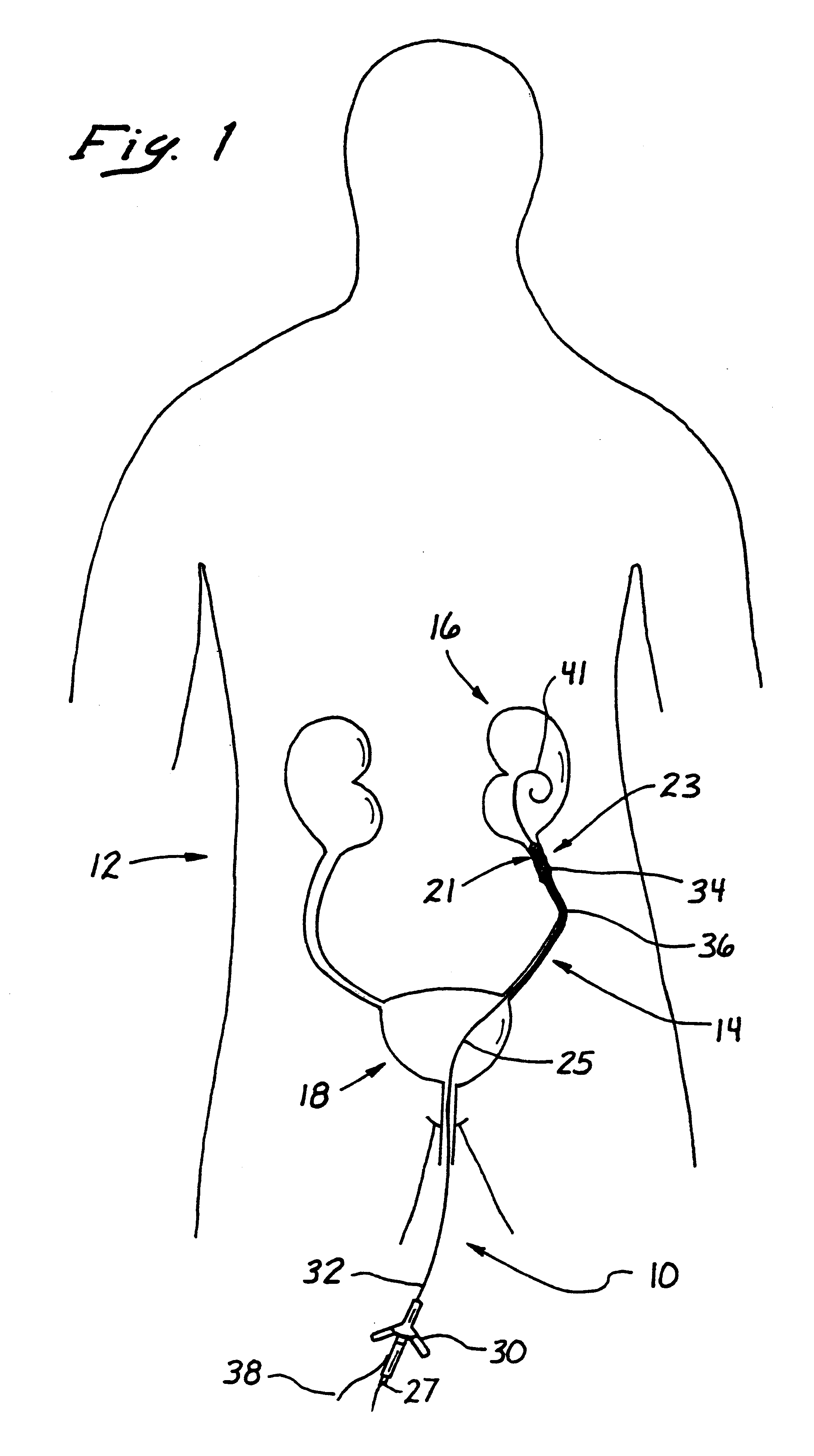
A catheter is illustrated in FIG. 1 and designated generally by the reference numeral 10. The catheter 10 is illustrated to be operatively disposed in a patient 12 having a ureter 14 extending between a kidney 16 and a bladder 18. The catheter 10 is adapted to increase the patency of the ureter 14, particularly at the upper pelvic junction 21 which is commonly occluded by strictures 23.

The catheter 10 typically includes an elongate tube 25 having a lumen 27 extending through a hub 30 at a proximal end 32, and an electrode assembly 34 at a distal end 36. The electrode assembly 34 is electrically energized through a conductor 38 at the proximal end 32. Operative placement of the catheter 10 can be facilitated by a guide catheter or a guidewire 41.

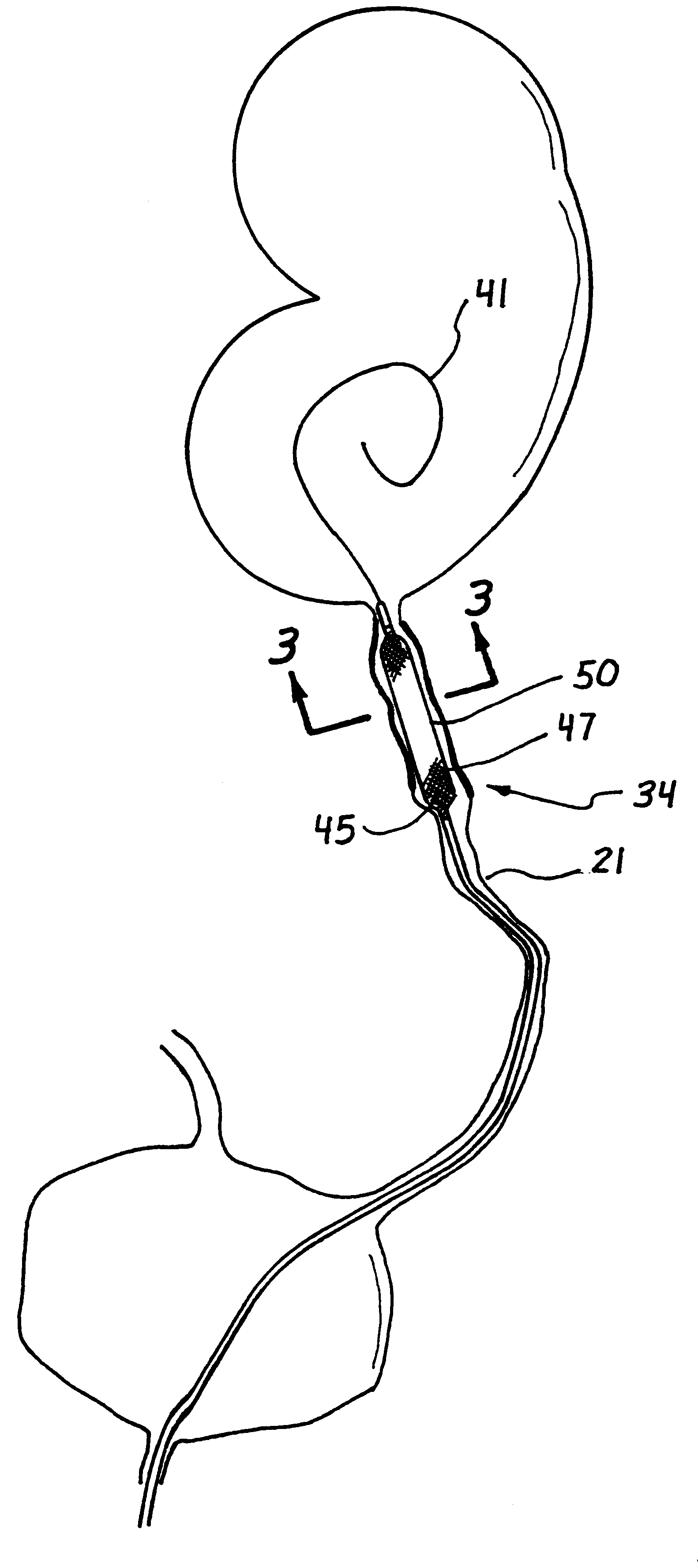
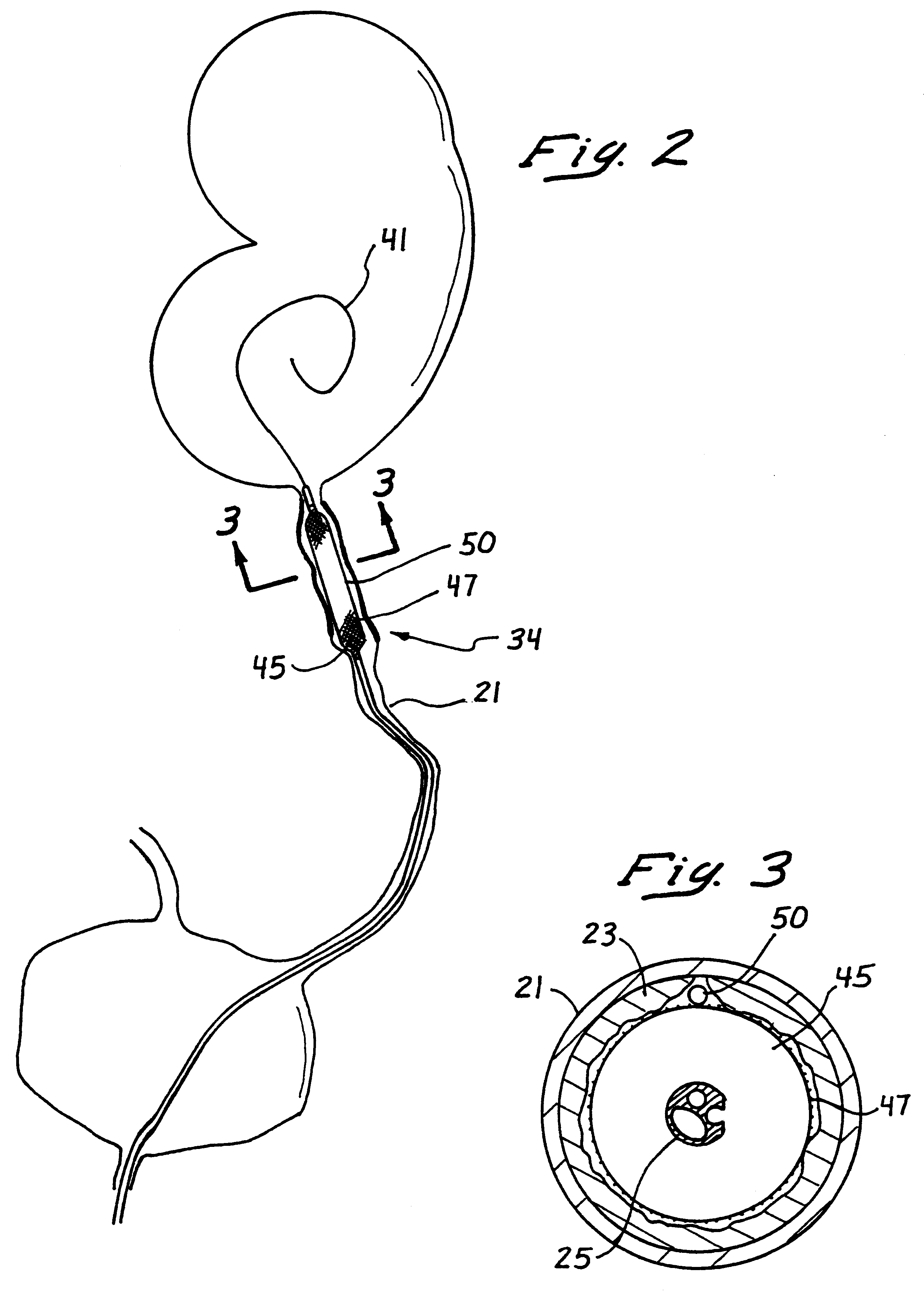
FIG. 2 shows an enlarged view of the upper pelvic junction 21 with the electrode assembly 34 including a balloon 45, a sheath 47 extending over the balloon 45, and an electrode 50. These elements are perhaps more easily identified in the radi...


PUM

PropertyMeasurementUnit
diameteraaaaaaaaaa
axial distanceaaaaaaaaaa
outer diameteraaaaaaaaaa

Abstract

A catheter adapted to increase the patency of a body conduit includes an elongate tube having an axis extending between a proximal end and a distal end, and a balloon disposed at the distal end of the tube and having properties for being expanded to a high-profile state and for being contracted to a low-profile state. A sleeve disposed over the balloon has a pair of ends disposed on opposing sides of a central section, the ends having a floating relationship relative to the tube with the central section disposed circumferentially of the balloon. An electrode disposed outwardly of the sleeve has properties for being electrosurgically energized to incise materials defining the body conduit when the balloon is in the high-profile state. The electrode can be formed of a plurality of elements stranded to increase the surface area of the electrode. The catheter can be inserted relative to a guide member having a conductor which carries the electrosurgical energy from the proximal end of the tube to the electrode at the distal end of the tube. An associated method includes the step of introducing electrosurgical energy into the conductor of the guide member to energize the electrode of the catheter.

Description

1. Field of the InventionThis invention relates generally to surgical devices and more specifically to electrosurgical catheters adapted to incise body material defining a body conduit.2. Discussion of the Prior ArtVarious surgical devices have been used to electrosurgically ablate or otherwise cut body materials. In this type of surgery, electrosurgical energy is passed between two electrodes creating a high current density which ablates the body materials. In a typical monopolar system, the patient is coupled to a large grounding pad which forms one of the electrodes. The electrosurgical device forms the other electrode. In this system, the electrosurgical device provides a very low surface area and consequently a very high current density for ablation or cutting in proximity to the device. In a bipolar system, the two electrodes are included in the device and high current density is achieved in the small area between the electrodes.These electrosurgical devices include a catheter...

Claims


Application Information

Patent Timeline
Patent Type & Authority Patents(United States)
IPC IPC(8): A61B18/14
CPCA61B18/1492A61B2017/22038A61B2018/00077A61B2018/00083A61B2018/00148A61B2018/00214A61B2018/0022A61B2018/00285A61B2018/0041A61B2018/00505A61B2018/162
Inventor HART, CHARLES C.HILAL, NABILEWERS, RICHARD C.PRAVONGVIENGKHAM, BOUNSAVANH
Owner APPL MEDICAL RESOURCES CORP
Why Eureka
Try Eureka