Loop latency compensated PLL filter

a filter and loop latency technology, applied in the field of loop latency compensation, can solve the problems of reducing the sensitivity of large bursty noise, affecting the synchronization speed of the synchronizer, and the inherent presence of loop delay in the time synchronizer, so as to reduce the jitter of the pll circuit, reduce the sensitivity to large bursty noise, and improve the synchronization speed

Inactive Publication Date: 2001-05-22
MAXTOR
View PDF5 Cites 60 Cited by
  • Summary
  • Abstract
  • Description
  • Claims
  • Application Information

AI Technical Summary

Benefits of technology

In loop latency compensated PLL filter, two additional feedback terms, a state compensation and a delayed phase compensation signal, are provided as input of a proportional integral filter (PI filter) of loop latency compensated PLL. Accordingly, the PI filter input comprises two additional compensation input signals: the delayed phase signal and the state signal, in addition to a phase estimated error output from a phase detector, that are coupled to the input of the PI filter. Consequently, PI filter thus is able to provide a latency compensated phase error control output that is fedback to control a phase mixer to generate a square waveform used to drive an A / D of the PLL in accordance with the principles of this invention. The loop latency compensated PLL of this invention thus minimizes the jitter of the PLL circuit, provides higher format efficiency, and also has reduced sensitivity to large bursty noises.

Problems solved by technology

Typical PLL filter designs based on frequency response techniques cannot handle time varying filters and hence generate sub-optimal results.
An undesirable property of many discrete-time synchronizers is the inherent presence of loop delay, such as described in "Effect of Loop Delay on Stability of Discrete-Time PLL", J. W. M. Bergmans, IEEE Transactions on Communications, vol.
4, April 1995, which not only makes the synchronizer less stable but also degrades the performance of the synchronizer.

Method used


Image

  • Loop latency compensated PLL filter
  • Loop latency compensated PLL filter
  • Loop latency compensated PLL filter

Examples


Embodiment Construction

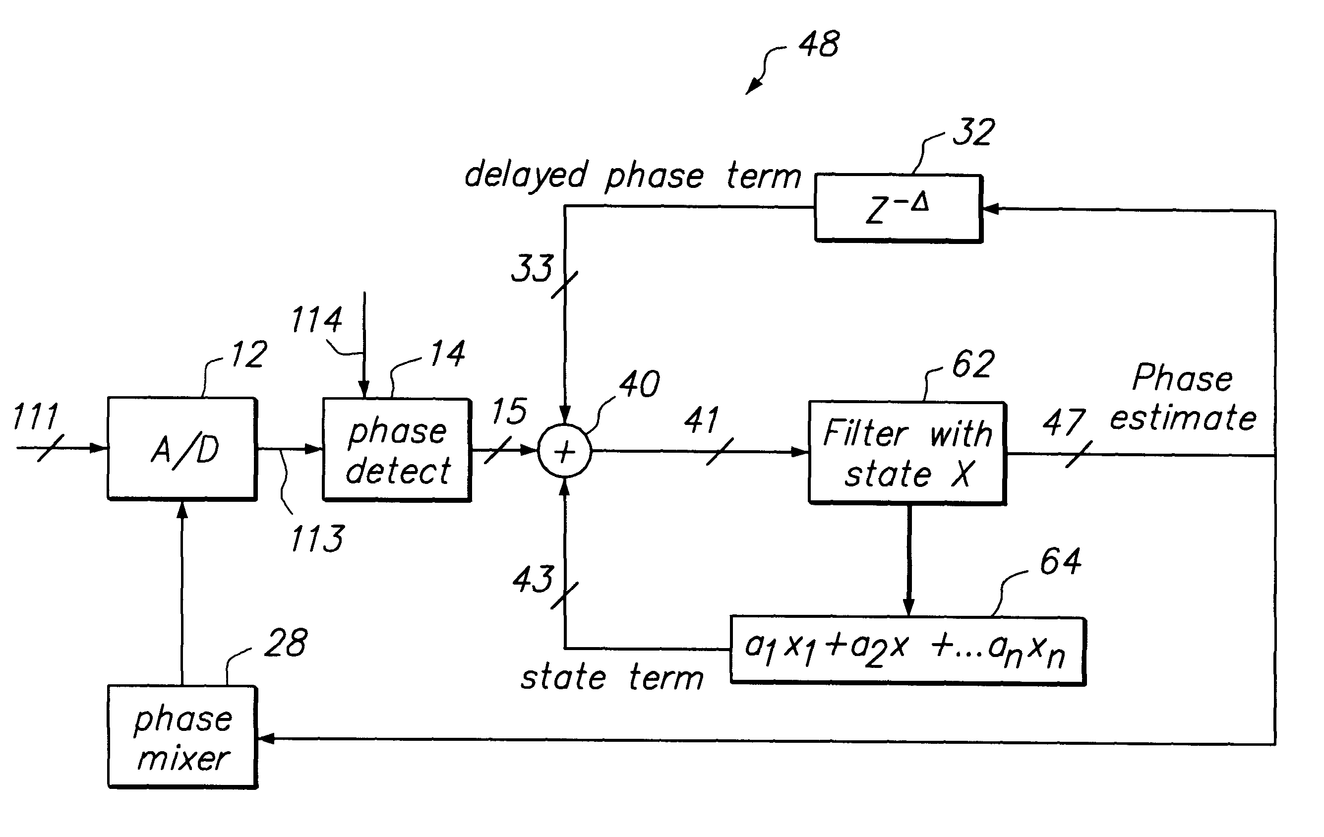
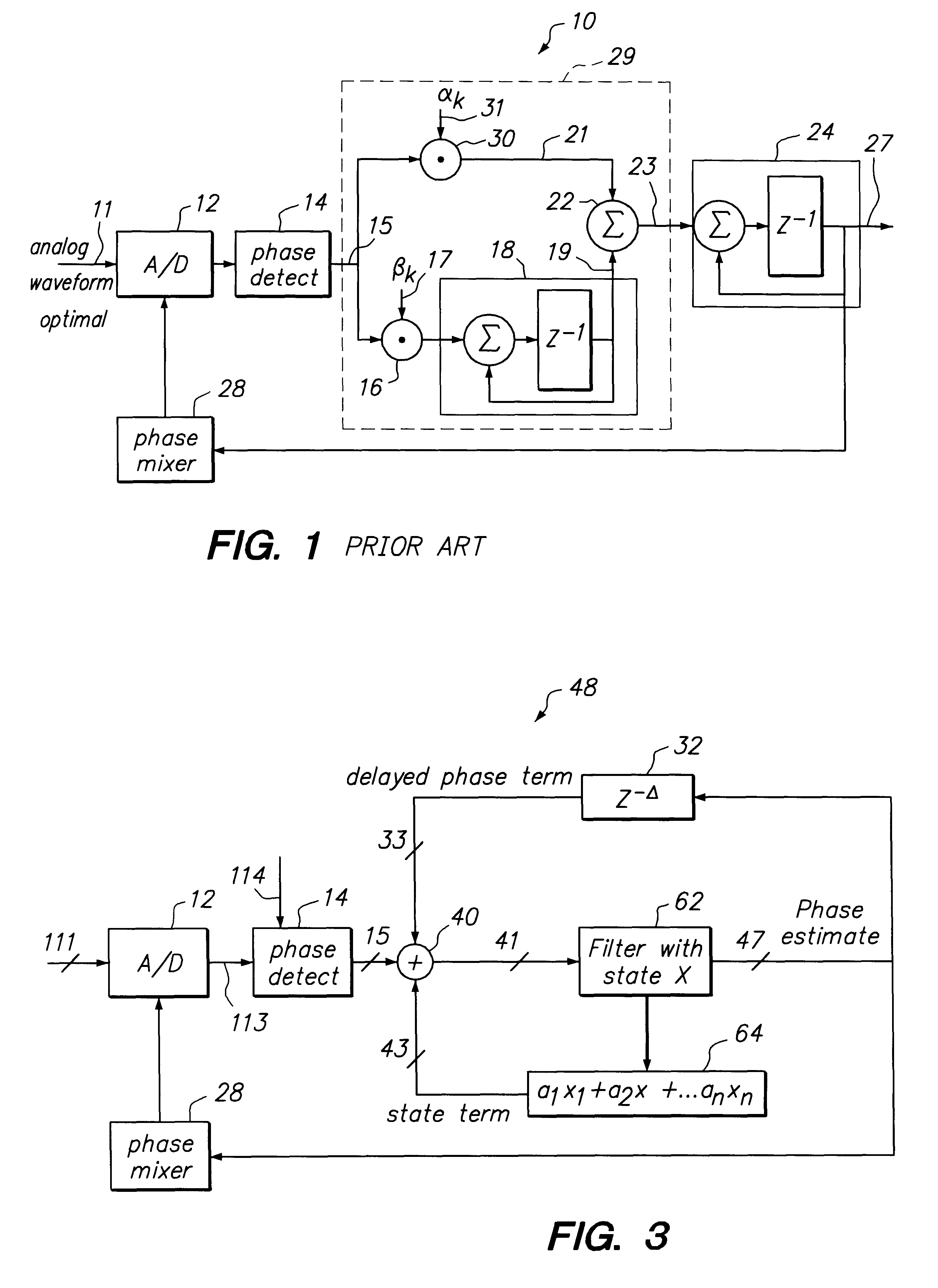
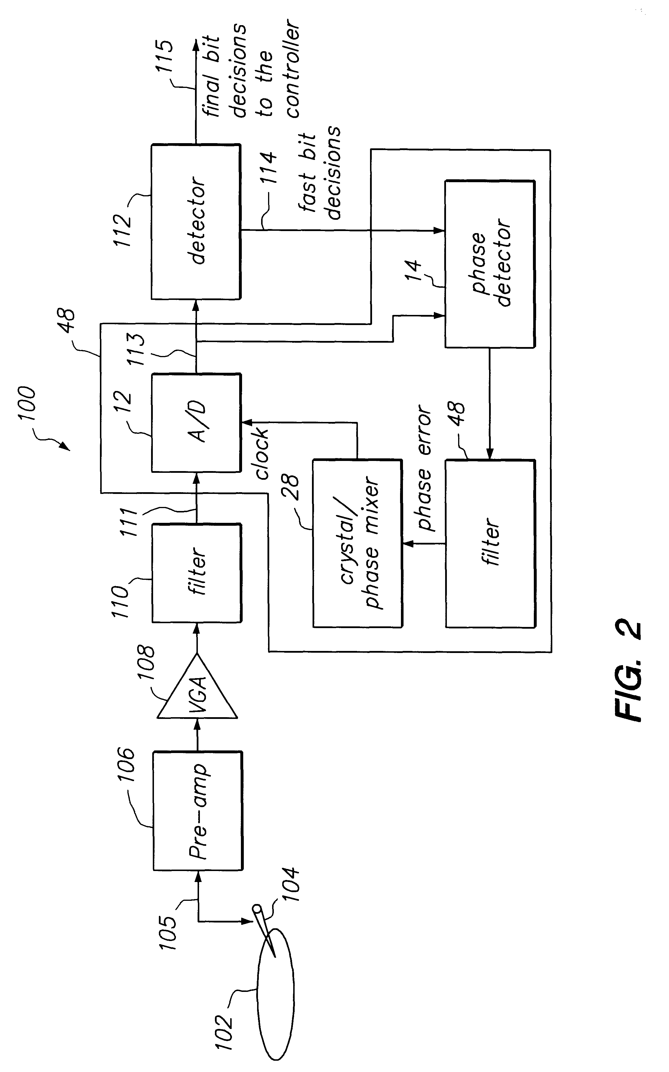
FIG. 2 illustrates a generalized block diagram of a storage media system having a loop latency compensated PLL filter provided according to the principles of this invention. Storage media system 100 comprises a storage media 102 coupled to a media head 104 for reading data signals from storage media 102. A pre-amplifier 106 (Pre-Amp) is coupled to receive read data signal 105 from head 104 and generate a corresponding amplified read data signal 106. A control amplifier (VGA) 108 is coupled to Pre-Amp 106 to receive the amplified data signal 106 and generate an associated corresponding controlled amplified data signal. A low-pass filter 110 is coupled to the VGA 108 to receive the controlled amplified data signal and generate an associated shaped analog data signal 111 having reduced high-frequency components. A low-latency compensated PLL filter 48, as is described in greater detail relative to FIGS. 2 and 3, is coupled to low-pass filter 110 receive as input the shaped analog input...


PUM

PropertyMeasurementUnit
phase erroraaaaaaaaaa
phaseaaaaaaaaaa
frequencyaaaaaaaaaa

Abstract

The loop latency compensated PLL filter comprising two additional feedback terms, a delayed phase compensation signal and a state compensation signal, that are provided as input of a PLL filter. Accordingly, the PLL filter input comprises two additional compensation input signals: the delayed phase compensation signal and the state compensation signal in addition to a phase estimated error output from a phase detector that is also coupled to the input of the PLL filter. Consequently, PLL filter thus is able to provide a latency compensated phase error control output that is fedback to control a phase mixer to generate a square waveform used to drive an A / D of the PLL in accordance with the principles of this invention. The loop latency compensated PLL of this invention thus minimizes the jitter of the PLL circuit, provides higher format efficiency, and also has reduced sensitivity to large bursty noises.

Description

Invention relates to phase-locked loop circuits (PLLs), and more particularly to PLLs in storage devices, such as disk drives.BACKGROUND OF INVENTIONIn the presence of initial disturbances such as phase and frequency steps, the optimal phase-locked loops (PLL) filter is known to have time varying form. Typical PLL filter designs based on frequency response techniques cannot handle time varying filters and hence generate sub-optimal results. It has been recognized for some time now that state space methods in general and Kalman filtering techniques in particular can be used to design and analyze synchronizers or PLL, such as surveyed in "Phase-Locked Loops," S. C. Gupta, Proceedings of the IEEE, vol. 63, no. 2, February 1975. More specifically, Kalman filtering theory enables us to derive optimal synchronizer structures for a given phase disturbance model, generate the time varying and steady state filter gain parameters, and calculate the time varying performance of the synchronizer...

Claims


Application Information

Patent Timeline
Patent Type & Authority Patents(United States)
IPC IPC(8): G11B20/14H03L7/091H03L7/093H03L7/08
CPCG11B20/1403H03L7/091H03L7/093
Inventor PATAPOUTIAN, ARA
Owner MAXTOR
Why Eureka
Try Eureka