Vane type hydraulic actuator

a hydraulic actuator and valve body technology, applied in the direction of valve arrangement, oscillating piston engine, machine/engine, etc., can solve the problems of high production cost, low productivity, complex apparatus, etc., and achieve the effect of reducing production cost and improving productivity

Inactive Publication Date: 2001-05-29
MITSUBISHI ELECTRIC CORP
View PDF4 Cites 17 Cited by
  • Summary
  • Abstract
  • Description
  • Claims
  • Application Information

AI Technical Summary

Benefits of technology

Another object of the present invention is to provide a vane type hydraulic actuator, in which a force can be imposed to the chip seals to contact tightly with its counter surface, without using a supplemental biasing force generating means, for example, a spring, so that the productivity can

Problems solved by technology

The vane type hydraulic actuator of the prior art has a drawback, due to such a structure, that a biasing force generating means, for example, a spring 47 is necessary for pressing the chi

Method used


Image

  • Vane type hydraulic actuator
  • Vane type hydraulic actuator
  • Vane type hydraulic actuator

Examples


embodiment 1

The embodiment 1 is explained below, referring to FIGS. 1-9.

The elements identical or equivalent with the elements in the explanation of the prior art are referred by the same reference numerals, and their explanation is omitted.

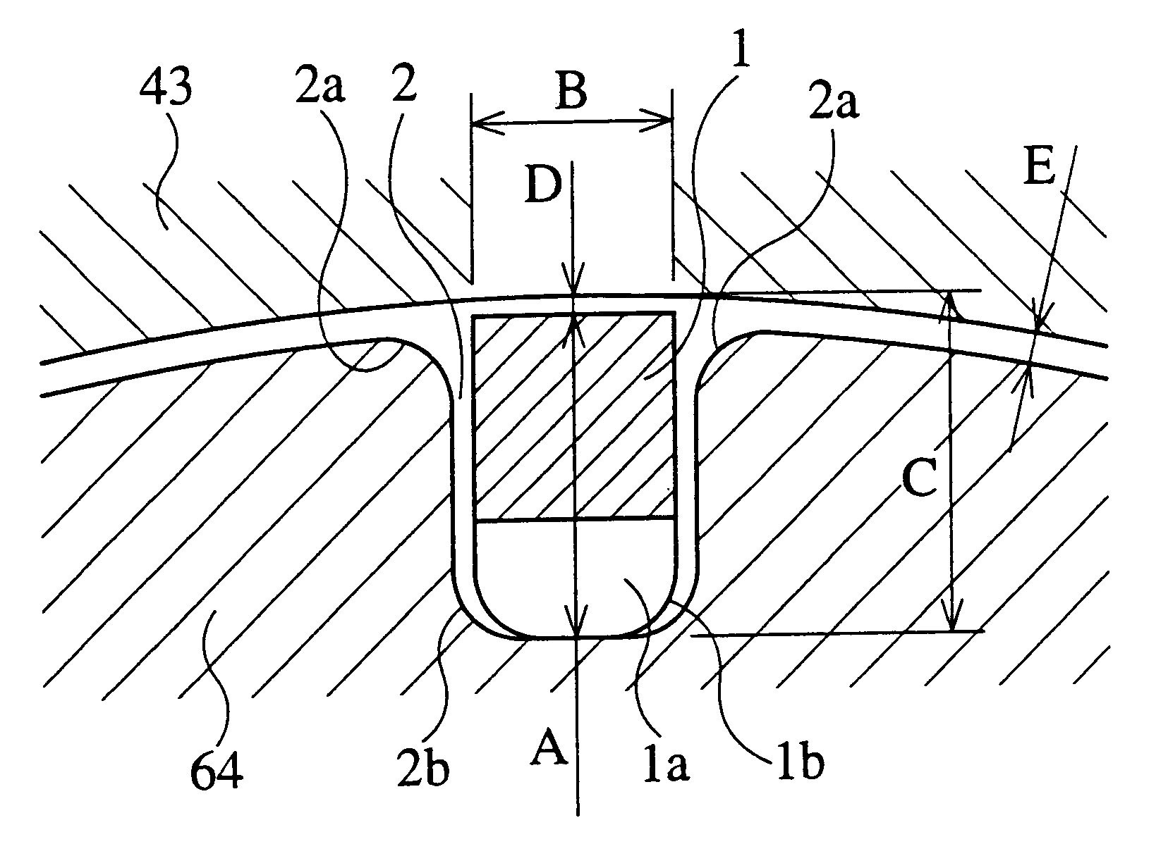
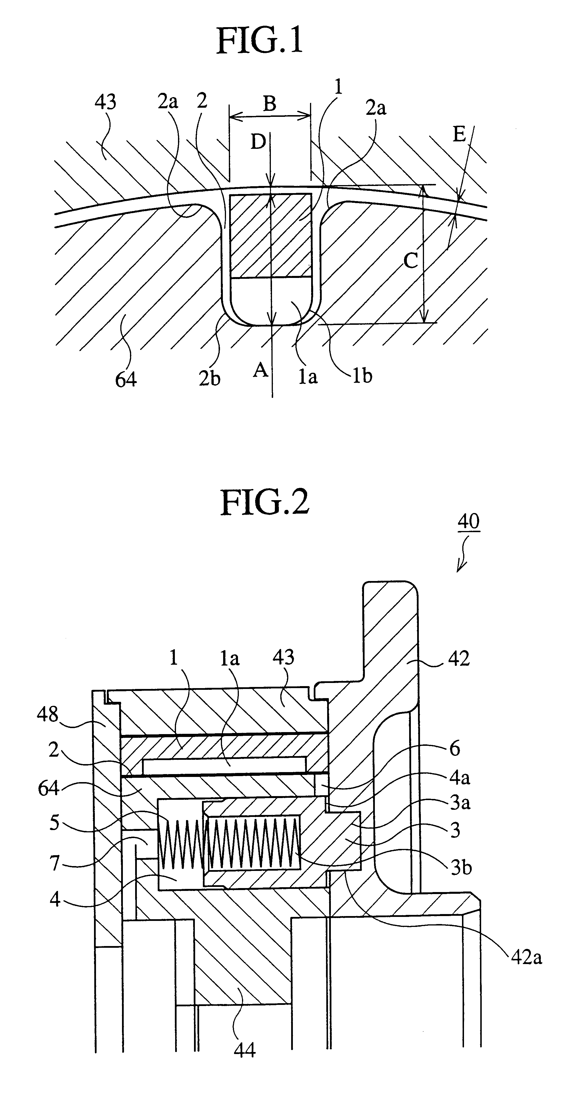
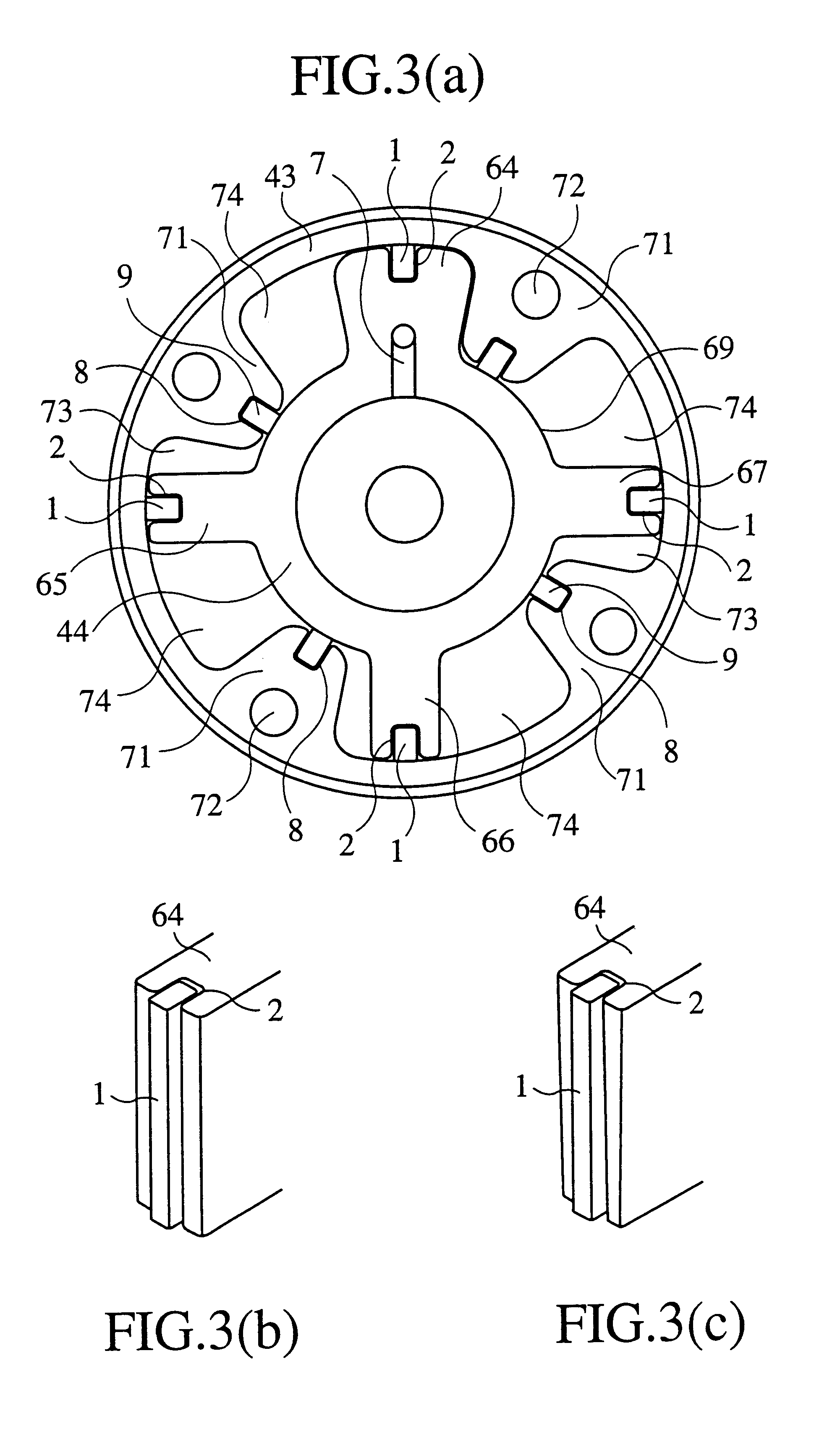
Reference numeral 1 denotes a chip seal as a sealing element. The chip seal 1 is formed as a substantially square prism. Perspective views of the chip seal are shown in FIG. 5. The chip seal 1 can have a recessing portion 1a at its bottom. And its both end portions can be chamfered, as shown in FIG. 5(a). However, the chip seal 1 can be a simple square prism bar having no recessing portion, as shown in FIG. 5(b).

Reference numeral 2 denotes a seal groove for receiving the chip seal. The seal groove 2 is disposed at the tip of each vane 64-67. Perspective view of the seal groove and the chip seal received in it are shown in FIG. 3. The groove can be parallel with the rotor axis, namely the width can be constant, as shown in FIG. 3(b). However, the groove can b...

embodiment 2

The explained, supposing that the chip seal 1 has a recessing portion 1a. However, the recessing portion 1a is not inevitable for the chip seal 1.

Embodiment 3

The embodiment 3 is explained below, referring to FIGS. 18-22.

The chip seal 1 has a hollow portion 1c at its bottom side, so that the center of the gravity of the chip seal 1 as well as the oil pressure acting plane become nearer to the inner surface of the case 43. The structure of the other part of the hydraulic actuator of this embodiment is identical to that of the embodiment 2, thus their explanation is omitted here for avoiding the redundancy.

The function of the chip seal according to the embodiment 3:

The essential functions are similar to that of the embodiment 2. The different point is that the oil pressure acting plane becomes nearer to the inner surface of the case 43, because the working oil can enter into the hollow portion 1c at the bottom portion of the chip seal. The acting plane of the force to displace the chip...

embodiment 3

The explained, supposing that the chip seal 1 has a shape shown in FIG. 18, however the shape of the chip seal 1 is not limited to this form. For example, the chip seal 1 may have a hollow portion 1c at its bottom as well as a concave recessing portion 1d at its side surface, as shown in FIG. 22. Also, such a chip seal has effects similar to that of ship seal shown in FIG. 18. The working oil can flow easily into the hollow portion 1c through the concave recessing portion 1d, thus a stable sealing force can be promptly obtained and assured. The material cost for the chip seal can be reduced, without reducing the tolerable strength. However, it shall be noted that the hollow portion 1c is not inevitable. For example, the chip seal can have a shape as shown in FIG. 5(b).

An advantage of the present invention is that the sealing element can be pressed to the counter surface by the oil pressure, without using a supplemental pressing means, for example, a spring in the prior art. Therefor...


PUM


Abstract

A vane type hydraulic actuator, wherein a chip seal 1, as a seal element between the case 43 and the rotor 44, can be pressed to contact tightly with the counter surface, without using a spring 47 as in the prior art, when a working oil is supplied either from the oil pressure chambers for timing retard or for timing advance. Simultaneously, the locking between the rotor 44 and the case 43 can be released. The hydrodynamic resistance at the gap between the tip of the seal element (chip seal) 1 and the counter surface of the seal element is made larger than that at the gap between the flank of the seal element 1 and the flank of the seal groove 2, which accomodates the seal element, so that the working oil of the hydraulic actuator flows between the flanks. The working oil at the bottom of the seal element urges the seal element to contact tightly with the counter surface. An oil channel 6 connects the bottom of the seal groove and a stopper pin holding hole 4, which holds a stopper pin 3 pressed by a spring 5. When a working oil is supplied from either of oil pressure chambers for timing retard or advance, the channel 6 opens to supply a working oil into the stopper pin holding hole 5 so as to displace the pin against the biasing force of the spring 5 to release the suppression of rotation.

Description

BACKGROUND OF THE INVENTION1. Field of the InventionThe present invention relates to a vane type hydraulic actuator for use, for example, in a valve timing adjusting apparatus, which controls the timing of opening and closing of an intake valve and / or exhaust valve of an engine, in response to the running condition of the engine.2. Description of the Prior ArtFIG. 23 is a cross sectional view of a vane type hydraulic actuator of the prior art, specifically, it is a vane type hydraulic actuator shown in Japanese Patent Application JP-A-314069 applied by the same applicant of this patent application. FIG. 24 is a detailed cross sectional view of the plunger portion of the actuator shown in FIG. 23, which is a main portion of the actuator. FIG. 25 is a cross sectional view of the plunger portion shown in FIG. 24, at a state when an oil pressure is applied.Reference numeral 19 denotes a cam shaft for an intake valve having a cam for the intake valve 19a. A timing pulley 21 is disposed a...

Claims


Application Information

Patent Timeline
IPC IPC(8): F01L1/344F01L1/34F15B15/12
CPCF01L1/3442F01L2001/3444F01L2001/34469F01L2001/34479
Inventor FUKUHARA, KATSUYUKISEKIYA, MUTSUO
Owner MITSUBISHI ELECTRIC CORP
Why Eureka
Try Eureka