
System and method for telemetrically providing intrabody spatial position

a technology of intrabody position and telemetry, which is applied in the field of system and method for providing intrabody spatial position, can solve the problems of affecting the patient's treatment, affecting the patient's comfort, and causing undue discomfort to the patient,

Inactive Publication Date: 2001-05-29
REMON MEDICAL TECH
View PDF2 Cites 1520 Cited by
  • Summary
  • Abstract
  • Description
  • Claims
  • Application Information

AI Technical Summary

Problems solved by technology

Although utilizing the core biopsy system along with surgery is currently the method of choice when dealing with breast cancers and various other cancers, such a method suffers from several crucial limitations.
Since there is large difference between the position and shape of the breast during mammography and surgery, images taken during mammography are unusable for stereotactic positioning during the surgical procedure, thus greatly complicating and prolonging the tumor removal procedure and leading to undue discomfort to the patient.
In addition, serious limitations of the above mentioned procedure result from the implantation of a long wire often present in the breast for many hours at a time while the patient awaits surgery.
The surgeon must follow this wire into the breast to the located tumor, although ideally, the entry pathway into the breast should be designed independently of the wire, since this implanted wire may not always represent the optimal entrance trajectory.
In addition, the presence of wire(s) extending outside the breast greatly increases the risk of infection.
A major hurdle facing the surgeon or radiologist in using minimally invasive surgical instruments has been the difficulty in visualizing and positioning such instruments.
The precision of image-based pre-surgical planning often greatly exceeds the precision of actual surgical execution.
Precise surgical execution has been limited to procedures, such as brain biopsies, in which a suitable stereotactic positioning frame is available.
The restricted applicability of such a frame or device has led many researchers to explore the use of robotic devices to augment a surgeon's ability to perform geometrically precise tasks planned from computed tomography (CT) or other available image data.
Machines are very precise and untiring and can be equipped with any number of sensory feedback devices.
Although combining the skills of a surgeon with a robotic device can substantially increase the effectiveness and precision of various surgical procedures, such a robotic surgical device must have a precisely defined frame of reference, such as body coordinates, without which it cannot operate with precision.
Although using extracorporeal referencing devices and methods is advantageous for being non invasive, such positioning means are limited by the fact that the position of intrabody regions of interest constantly change, either due to deformation of elastic structures (e.g., the breast, organs inside the abdominal cavity) or due to the progression of the disease (e.g., intracranial swelling).
Thus, stereotactic methods cannot be used for precise and automated medical procedures, especially those relating to soft tissue.
This system suffers from several limitations resultant from the extracorporeal wire connection of the implanted reference transducer.
The use of such wires prevents the use of this design in intracranial applications, such as, for example, intracranial surgery.
A further limitation of this design is that wired devices cannot be left inside the body, but instead, have to be removed within a relatively short time following the procedure.
The removal procedure, which may necessitate full surgery, can be more traumatic to the patient than the insertion.
In addition, since discomfort to the patient is wantedly minimized, such wires have to be thin, and as such fragile, and can break during the surgical procedure.
Such a sudden loss of positioning information in the course of a surgical procedure can lead to catastrophic results.
In addition to the limitations imposed by the wiring of the reference transducer, a further disadvantage of the above mentioned method is that it yields only positions relative to external reference points provided by the reference transducers which are placed in contact with the patient's skin.
Such a system is rendered unusable in some surgical procedures.
Such air gaps either cut off ultrasonic communication between the reference and mobile transducers, or change the intra-body acoustic propagation conditions so that precise positioning information is hard to obtain.
In these systems and methods, the implants comprise a passive structure which is limited in properties to a specific imaging system.
However, each marker type can only be used with a specific imaging system, which greatly limits the application of such markers.
Furthermore, MRI and CT systems are bulky, intrusive and complicated to operate.
Finally, ultrasonic imaging systems, for the most part, do not yield independent 3D positions, and suffer from the disadvantages detailed above.
However, it does share most of the disadvantages of other fiducial marker methods.
In addition, it requires an independent power source, such as a battery, which limits its lifespan and increases the size of such a transponder.
Thus, a limitation common to all of the above mentioned positioning systems and methods is the lack of precise, telemetric, spatial localization of intrabody regions provided as information which is usable as machine input.

Method used


Image

  • System and method for telemetrically providing intrabody spatial position
  • System and method for telemetrically providing intrabody spatial position
  • System and method for telemetrically providing intrabody spatial position

Examples


examples

Reference is now made to the following examples, which together with the above descriptions, illustrate the invention in a non limiting fashion.

For purposes of better understanding the construction and operation of an acoustic transducer utilizable by the system of the present invention, reference is made to the construction and operation of an acoustic transducer as described in U.S. patent application Ser. No. 09 / 000,553.

Referring again to the drawings, FIGS. 5a, 5b and 6a-6e illustrate a preferred embodiment of a transducer element according to the present invention. As shown in the Figures, a transducer element 1 includes at least one cell member 3 including a cavity 4 etched into a substrate and covered by a substantially flexible piezoelectric layer 2. Attached to piezoelectric layer 2 are an upper electrode 8 and a lower electrode 6, the electrodes for connection to an electronic circuit.

The substrate is preferably made of an electrical conducting layer 11 disposed on an elec...


PUM


Abstract

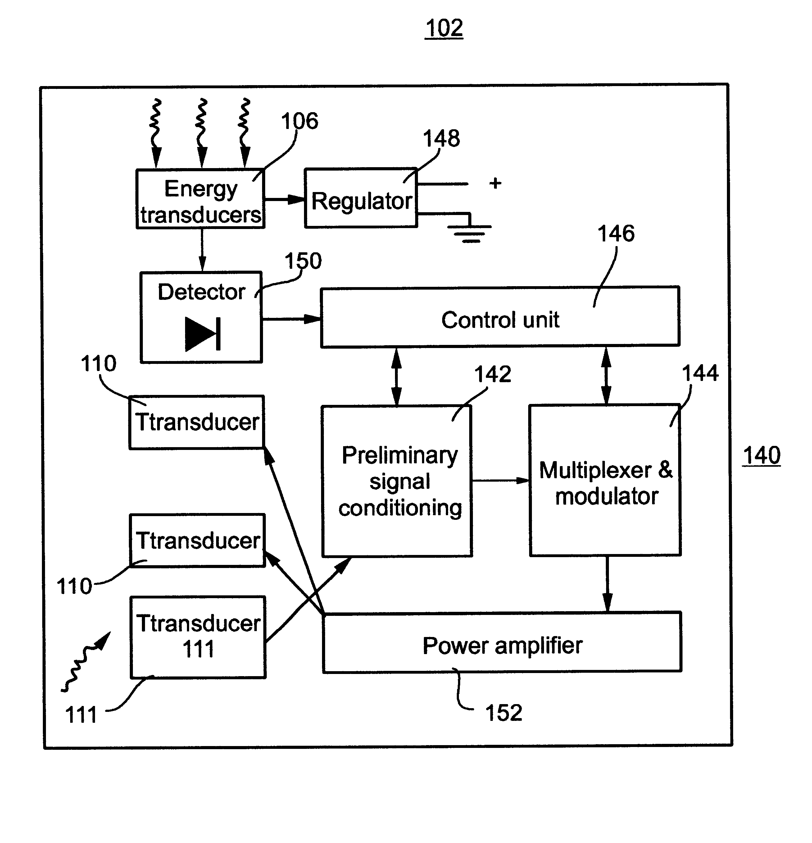
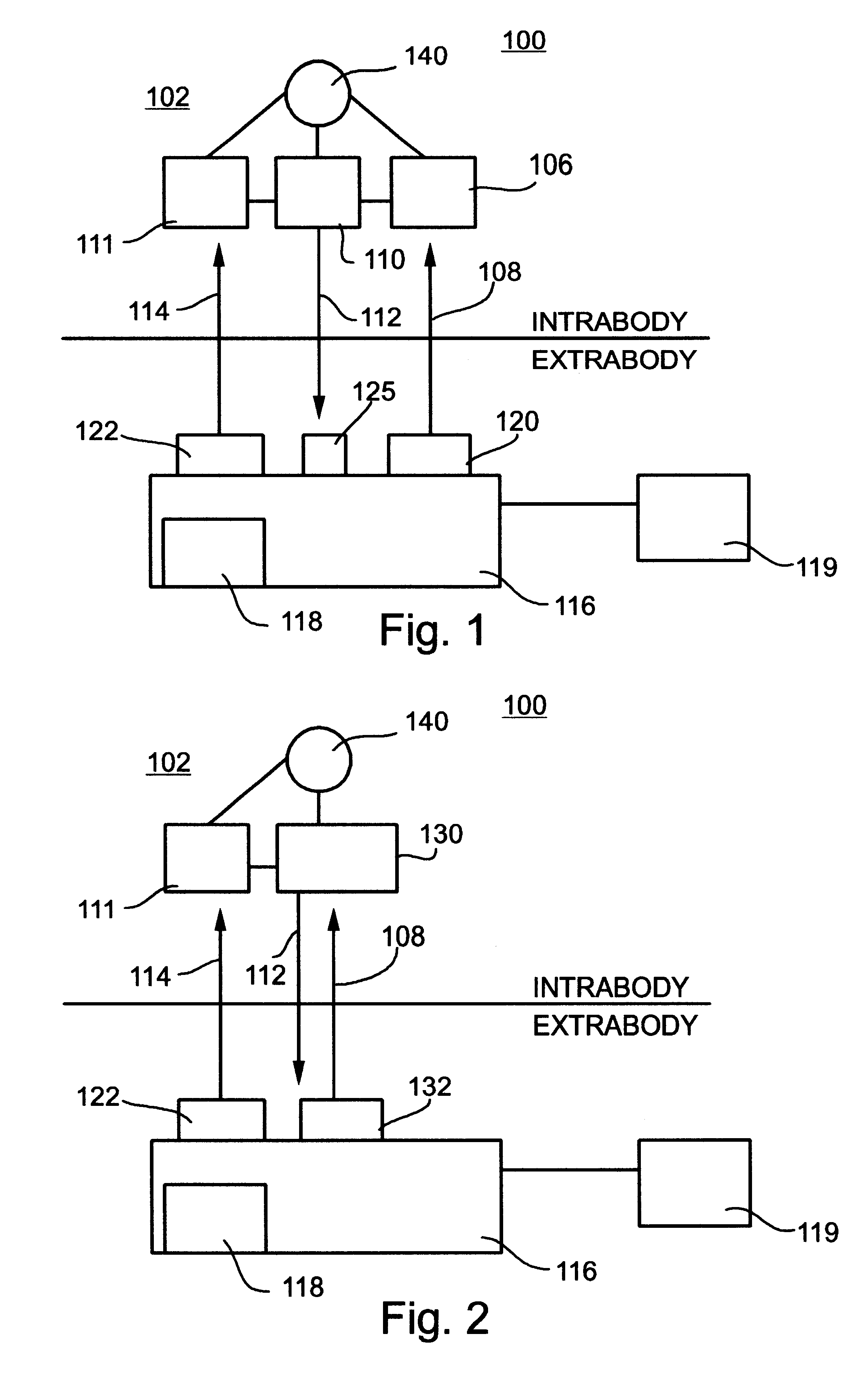
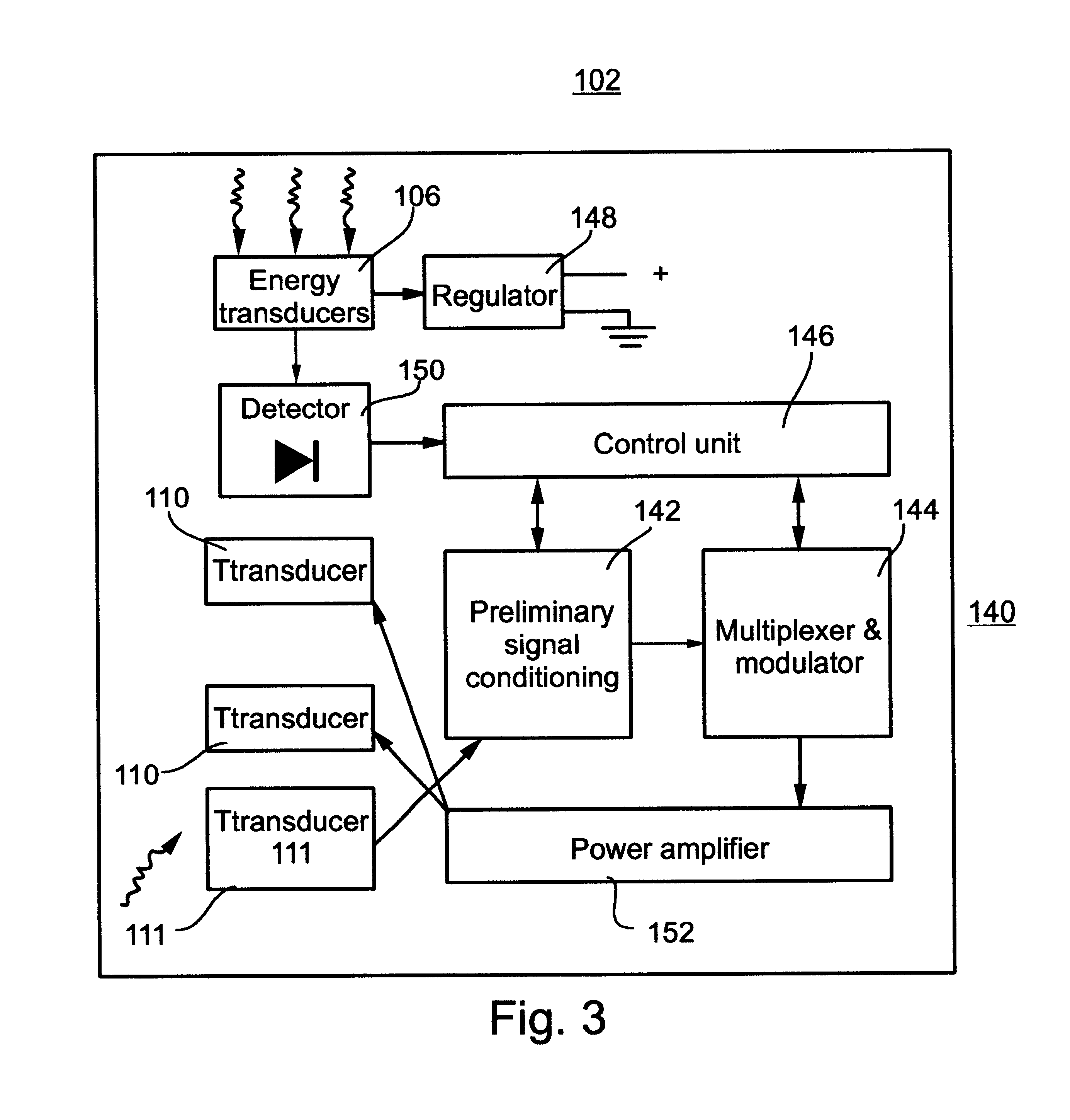
A telemetry system and method for providing spatial positioning information from within a patient's body are disclosed. The system includes at least one implantable telemetry unit which includes (a) at least one first transducer being for converting a power signal received from outside the body, into electrical power for powering the at least one implantable telemetry unit; (b) at least one second transducer being for receiving a positioning field signal being received from outside the body; and (c) at least one third transducer being for transmitting a locating signal transmittable outside the body in response to the positioning field signal.

Description

FIELD AND BACKGROUND OF THE INVENTIONThe present invention relates to a system and method for positioning a medical instrument and / or directing a medical procedure within a patient's body. More particularly, the present invention relates to an internal power source free transponder, transplantable within the body, which, in response to a positioning field signal, relays a locating signal outside the body, thereby enabling the precise localization of the transponder within the patient's body.Various medical procedures require precise localization of the three-dimensional position of a specific intra body region in order to effect optimized treatment.For example, localization and sampling of a suspected tumor is effected in breast biopsy procedures, by typically using a system known as a core biopsy system. The core biopsy system first obtains a stereo-mammogram from a patient's breast, while the breast is immobilized by being compressed between two plates. The stereo-mammogram is use...

Claims


Application Information

Patent Timeline
IPC IPC(8): A61B5/00A61B5/053G01F1/34G01F1/72G01F1/36H01L41/113H04R17/00H03H9/17H10N30/20H10N30/30
CPCA61B5/0031A61B5/0535A61B5/413G01F1/36G01F1/72H01L41/1132H04R17/00A61B2562/028A61N1/37288Y10S128/903H10N30/302
Inventor DORON, EYALPORAT, YARIVPENNER, AVI
Owner REMON MEDICAL TECH
Learn More