
Method and apparatus for controlling the temperature stability of an inductor using a magnetically coupled metallic object

a technology of magnetically coupled metallic objects and temperature stability, which is applied in the direction of material magnetic variables, using reradiation, instruments, etc., can solve the problems of temperature stability problems, proximity probes operating under very adverse physical conditions, and not always providing satisfactory solutions

Inactive Publication Date: 2001-06-12
BENTLY NEVADA INC
View PDF30 Cites 16 Cited by
  • Summary
  • Abstract
  • Description
  • Claims
  • Application Information

AI Technical Summary

Benefits of technology

Another further object of the instant invention is to provide a method and apparatus as characterized above which provides a significant degree of freedom for setting the temperature response of a series resistance of a sensing coil.
Another further object of the instant invention is to provide a method and apparatus as characterized above which eliminates the dependency on the use of low temperature coefficient of resistance (T.sub.cr) wire to form the sensing coil and thus, the relatively high resistance value typically associated with this wire that sacrifices the coil Q.
Another further objet of the instant invention is to provide a proximity probe as characterized above which provides improved overall system temperature stability.
Another further object of the instant invention is to provide a proximity probe that has an improved linear range provided by a substantial reduction in the temperature drift error of the transducer.
Another further object of the instant invention is to provide an eddy current proximity probe that precludes the false appearance of gap movement between the target being monitored and the sensing coil due to temperature.
Another further object of the instant invention is to provide an eddy current proximity probe as characterized above which is capable of being mass produced without appreciable alterations in temperature performance from one proximity probe to the next.

Problems solved by technology

However, these efforts have not always provided a satisfactory solution to the problem of controlling the temperature stability of an inductor in a multiplicity of these applications.
Specifically, there is a temperature stability problem of an inductor employed in a proximity probe utilized for machine monitoring as a result of, inter alia, the severe temperature predations of the environment.
In this environment the proximity probe must operate under very adverse physical conditions.
Moreover, the sensing coil of the proximity probe usually contains sources of temperature drift error which are attempted to be compensated for in the final product, usually at the expense of additional circuitry.
A principal source of the temperature drift error in the sensing coil is due to a temperature dependent resistance of the coil.
This temperature dependent resistance of the sensing coil effects a source of temperature drift error resulting in inaccurate proximity probe measurements as a consequence of the false appearance of a gap change between the target and sensing coil.
Such inconsistencies in temperature stability of the proximity probe result in unpredictable and unreliable measurements even when the proximity probe is functioning in its linear range of operation.
For the foregoing reasons, there is a need for controlling the temperature stability of a sensing coil of a proximity probe to preclude temperature drift and the resultant false appearance of gap change which leads to inaccurate and unreliable measurements of machine operating characteristics.
Accordingly, this temperature dependent resistance of the sensing coil brings about a source of temperature drift error which results in inaccurate proximity probe measurements as a consequence of the false appearance of a gap change between the target object and coil.
Such inconsistencies in temperature stability of the proximity probe result in unpredictable and unreliable measurements even when the proximity probe is functioning in its linear range of operation.

Method used


Image

  • Method and apparatus for controlling the temperature stability of an inductor using a magnetically coupled metallic object
  • Method and apparatus for controlling the temperature stability of an inductor using a magnetically coupled metallic object
  • Method and apparatus for controlling the temperature stability of an inductor using a magnetically coupled metallic object

Examples


Embodiment Construction

Considering the drawings, wherein like reference numerals denote like parts throughout the various drawing figures, reference numeral 10 is directed to the temperature stable inductor according to the instant invention.

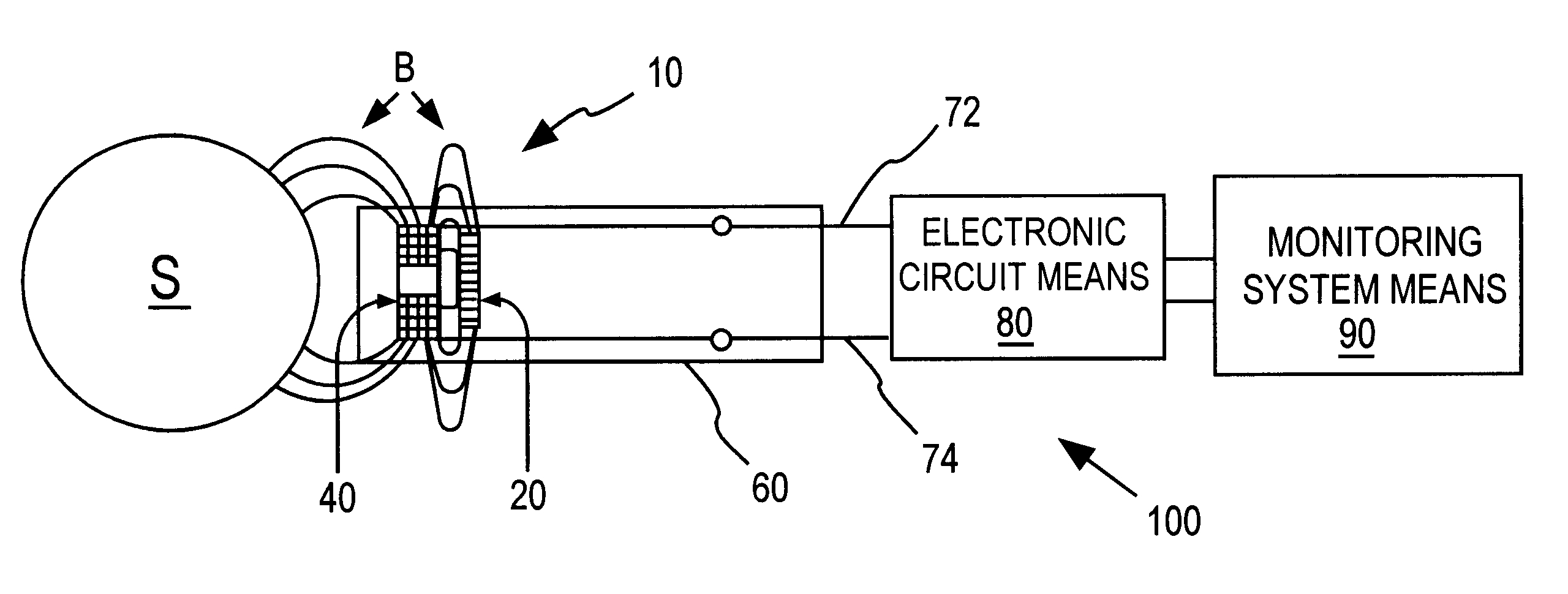
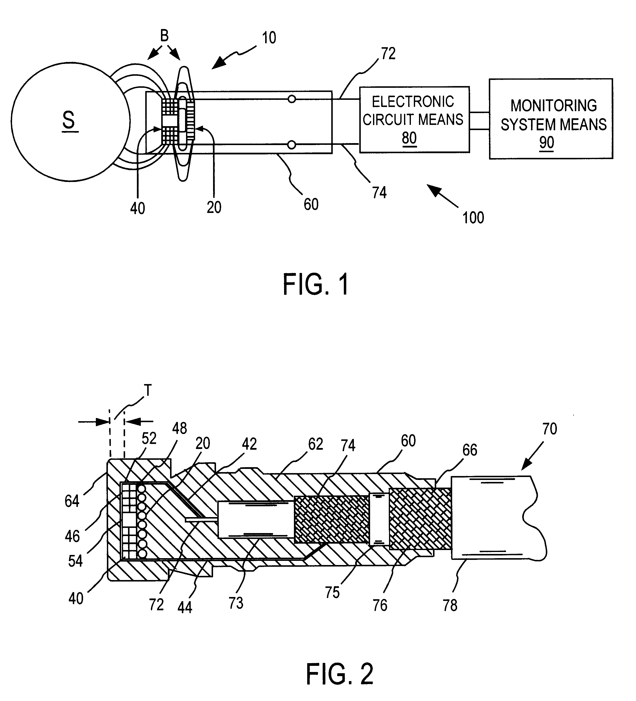
In its essence, and referring to the drawings, the temperature stable inductor 10 includes a metallic object 20 magnetically coupled to a coil or sensing element 40 by a magnetic field B emanating from the coil 40 for controlling the temperature stability profile of the coil.

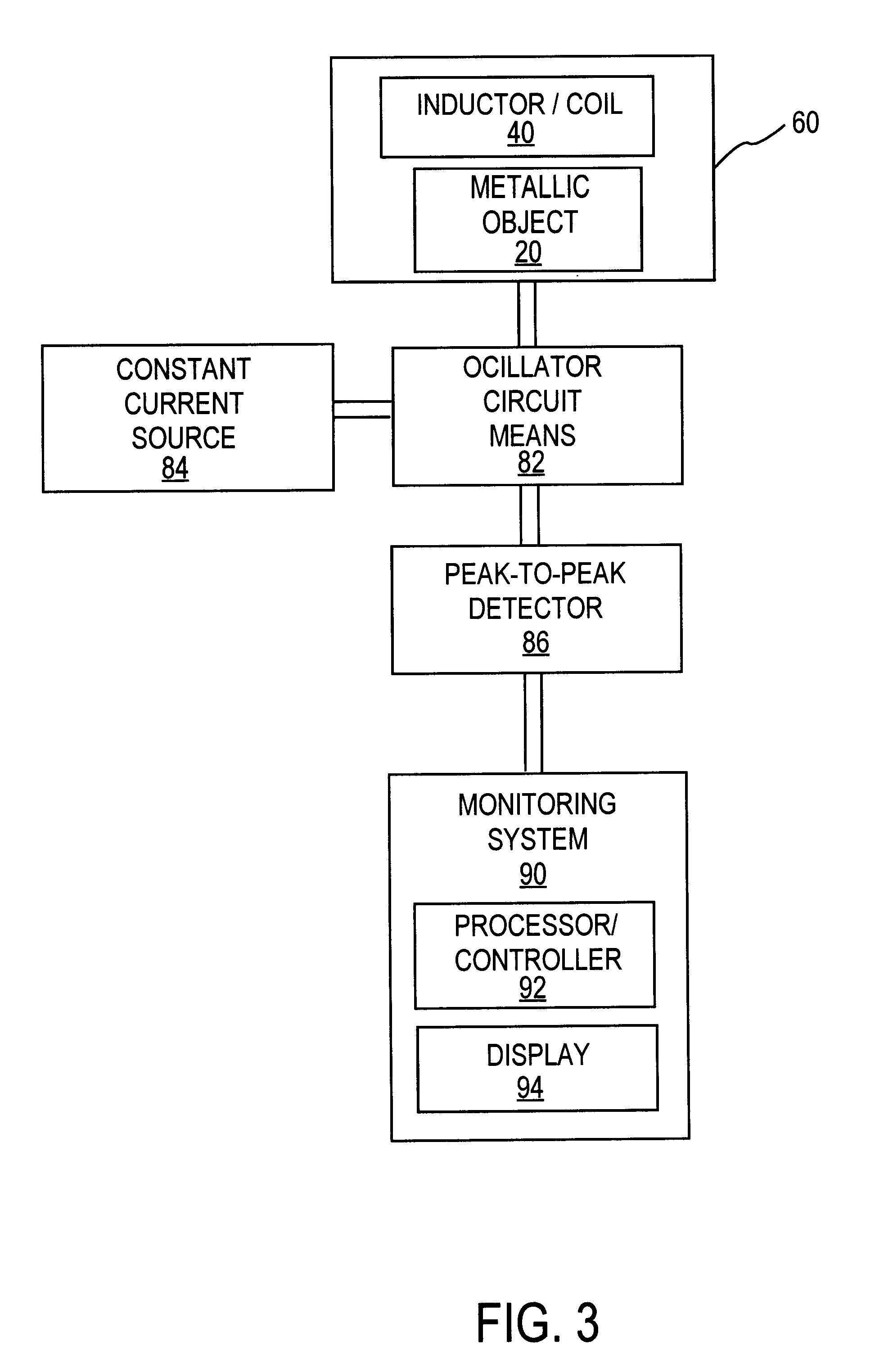
In one embodiment, and referring to FIG. 1, the temperature stable inductor 10 is tailored for use in a proximity probe 60 of a proximity probe system 100. The proximity probe system 100 monitors a target object, for example, a rotating shaft S of a machine and is comprised of the proximity probe 60 including the temperature stable inductor 10, an electronic circuit means 80 and a monitoring system 90. Typically, the proximity probe 60 is operatively coupled to the electronic circuit means 80 and ...


PUM


Abstract

A method and apparatus for controlling temperature stability of an inductor by using a magnetically coupled metallic object is disclosed in which a metallic object is magnetically coupled to the inductor by a magnetic field emanating therefrom. In one embodiment, the apparatus is tailored for use in a proximity probe of a machine monitoring system and includes the metallic object magnetically coupled to a sensing coil for controlling a resistance versus temperature profile including compensating for a proximity effect resistance of the coil.

Description

The instant invention relates generally to a method and apparatus for controlling the temperature stability of an inductor or transformer, and in particular, to a method and apparatus for controlling the temperature stability of a sensing coil of a proximity probe using a magnetically coupled metallic object.A variety of devices and methods have been developed in an effort to control the temperature stability of an inductor in a diversity of applications. However, these efforts have not always provided a satisfactory solution to the problem of controlling the temperature stability of an inductor in a multiplicity of these applications. Specifically, there is a temperature stability problem of an inductor employed in a proximity probe utilized for machine monitoring as a result of, inter alia, the severe temperature predations of the environment.To operate safely and efficiently, rotating and reciprocating machinery require the use of various transducers. One such transducer is an ed...

Claims


Application Information

Patent Timeline
Patent Type & Authority Patents(United States)
IPC IPC(8): G01D5/12G01B7/02G01D5/20G01D3/036G01D3/028G01V3/10
CPCG01B7/023G01D3/036G01D5/202G01V3/101
Inventor SLATES, RICH
Owner BENTLY NEVADA INC
Learn More