

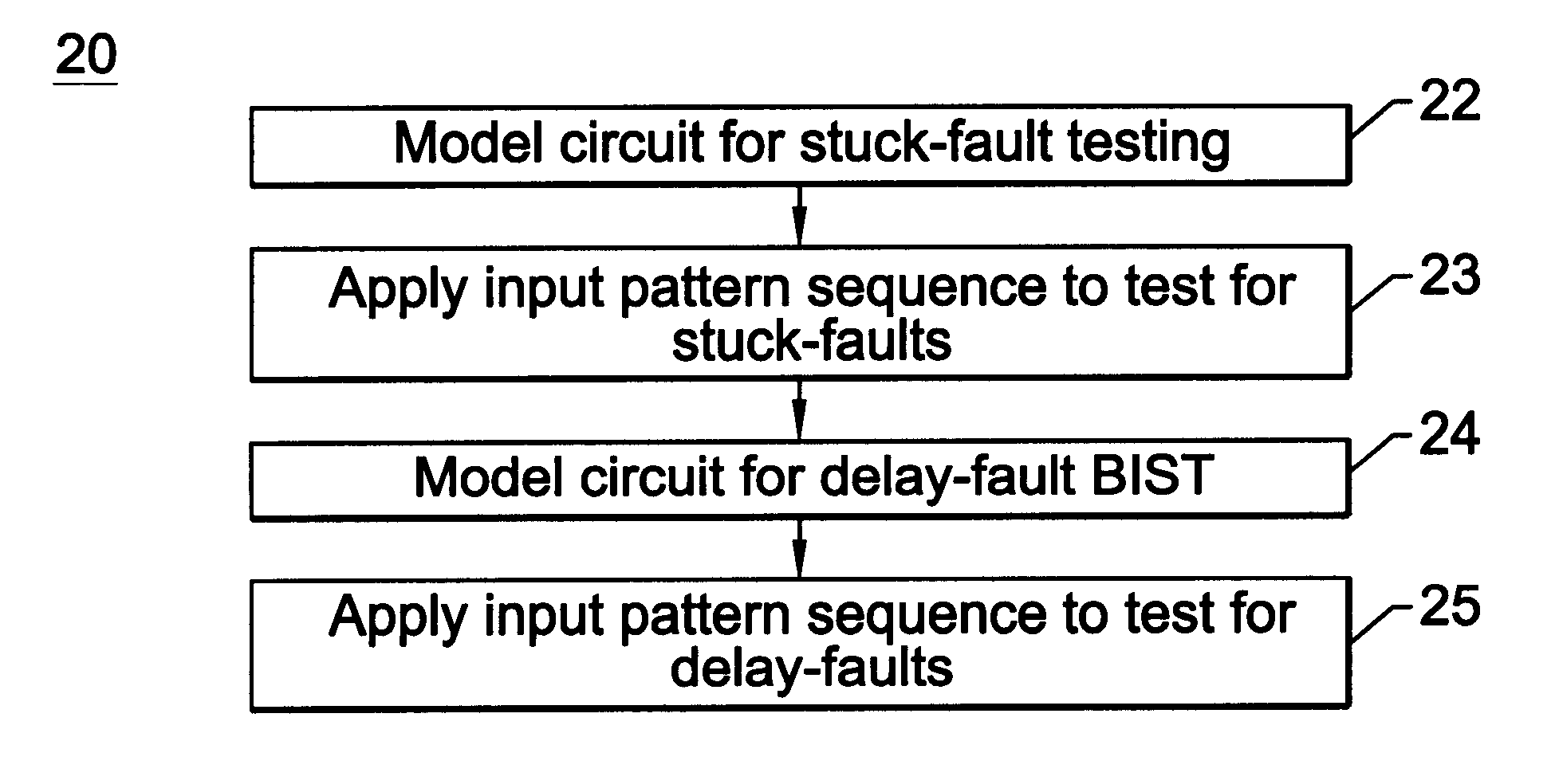
Method and apparatus for combined stuck-at fault and partial-scanned delay-fault built-in self test
a delay fault and built-in self-testing technology, applied in error detection/correction, transmission monitoring, instruments, etc., can solve problems such as path delay fault, reconvergent fanout circuit hazard, and hazard at hazardous node or ga
- Summary
- Abstract
- Description
- Claims
- Application Information
AI Technical Summary
Problems solved by technology
Method used
Image

Examples
Embodiment Construction
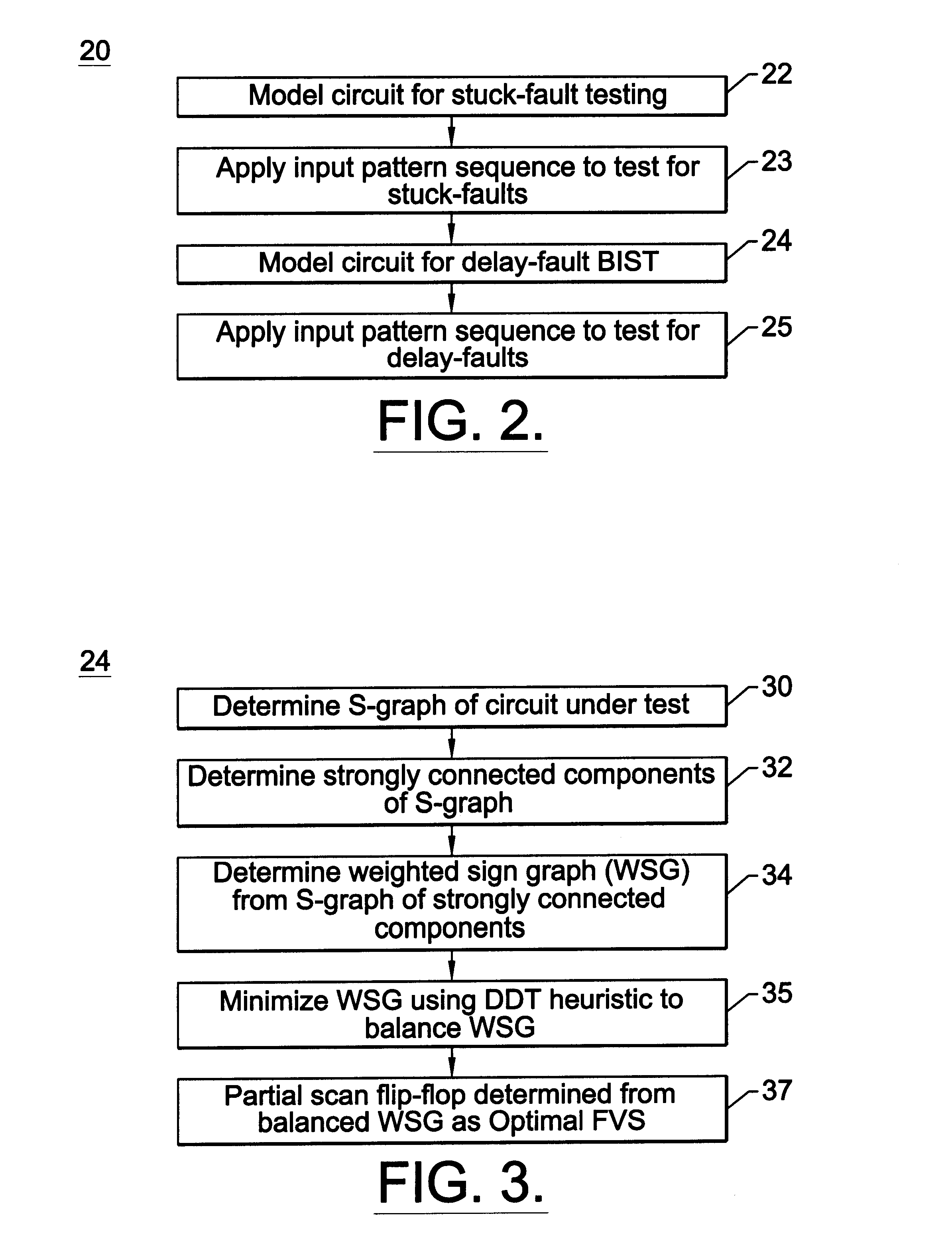
refers to results of Chakradhar, Agrawal described in S. T. Chadkradhar, A. Balakrishnan, and V. D. Agrawal, An Exact Algorithm for Selecting Partial Scan Flip-Flops. J. Electronic Testing: Theory and Applications, 7(1 / 2):83-94, August / October 1995. Example B refers to results of Lee and Reedy described in D. Lee and S. M. Reddy, On Determining Scan Flip-Flops in Partial-Scan Designs. In Proc. of the Int'l. Conf. on Computer-Aided Design, pages 322-325, November 1990. It is noted that Lee & Reedy did not publish cpu time. Example C refers to results of the method for combined stuck fault testing and partial scan delay fault built in self test 20 in which a depth-first weighting scheme was used to assign edge weight values in the WSG. In the method for combined stuck fault testing and partial scan delay fault built in self test 20, sequential false timing paths were not dropped. The method to eliminate short paths of the circuit under test 60 was performed to eliminate short paths th...
PUM
 Abstract
Description
Claims
Application Information