
Method of controlling arc welding processes and welder using same

a technology of arc welding and control arrangement, which is applied in the direction of arc welding apparatus, welding equipment, manufacturing tools, etc., can solve the problems of inability to accurately obtain control function, inability to control the dc gmaw welding process based on electrode stickout or ctwd, and inherent limitations of the control arrangement using the volt/ampere characteristics curve for the process, etc., to achieve accurate control function

Inactive Publication Date: 2001-06-19
LINCOLN GLOBAL INC
View PDF5 Cites 105 Cited by
  • Summary
  • Abstract
  • Description
  • Claims
  • Application Information

AI Technical Summary

Benefits of technology

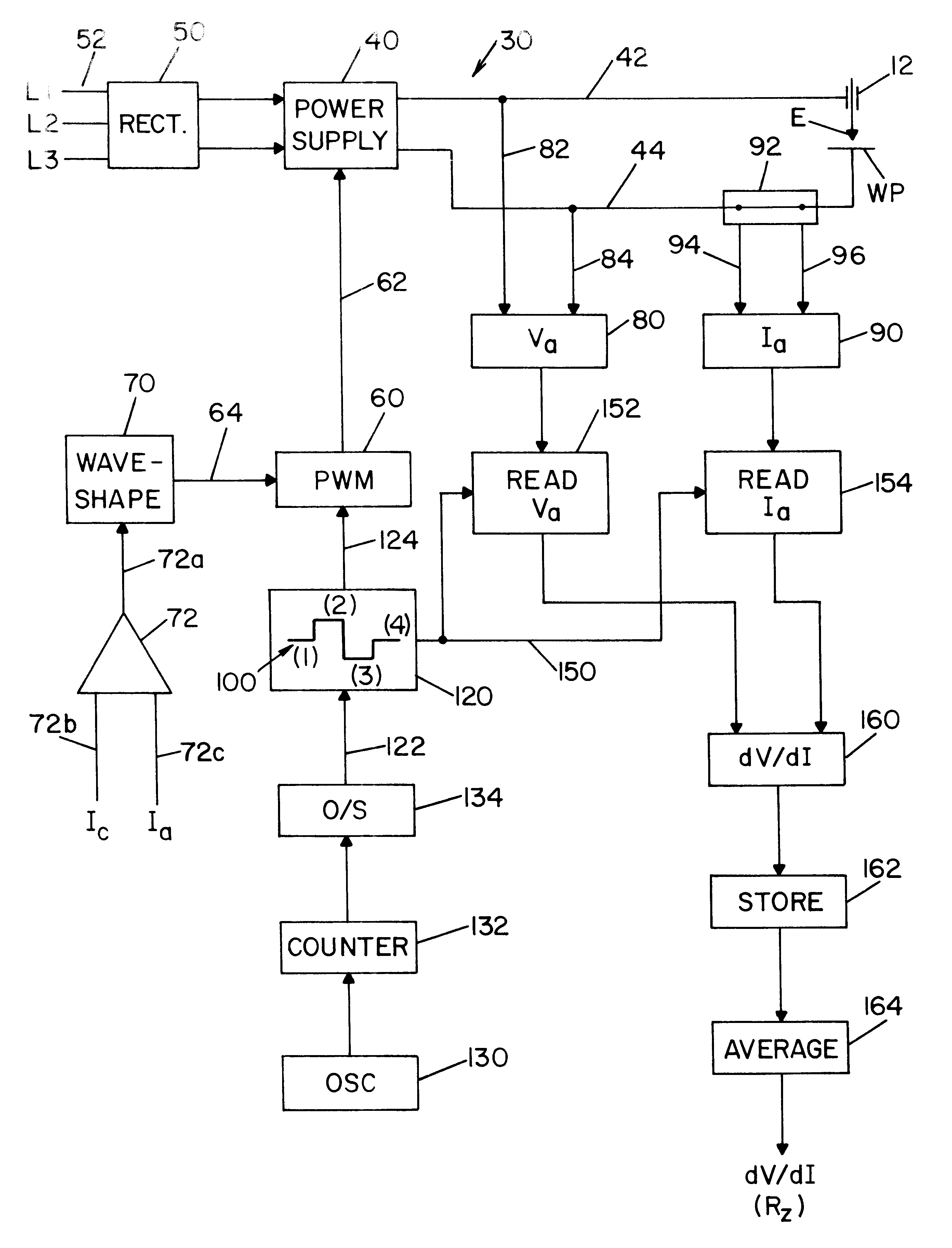
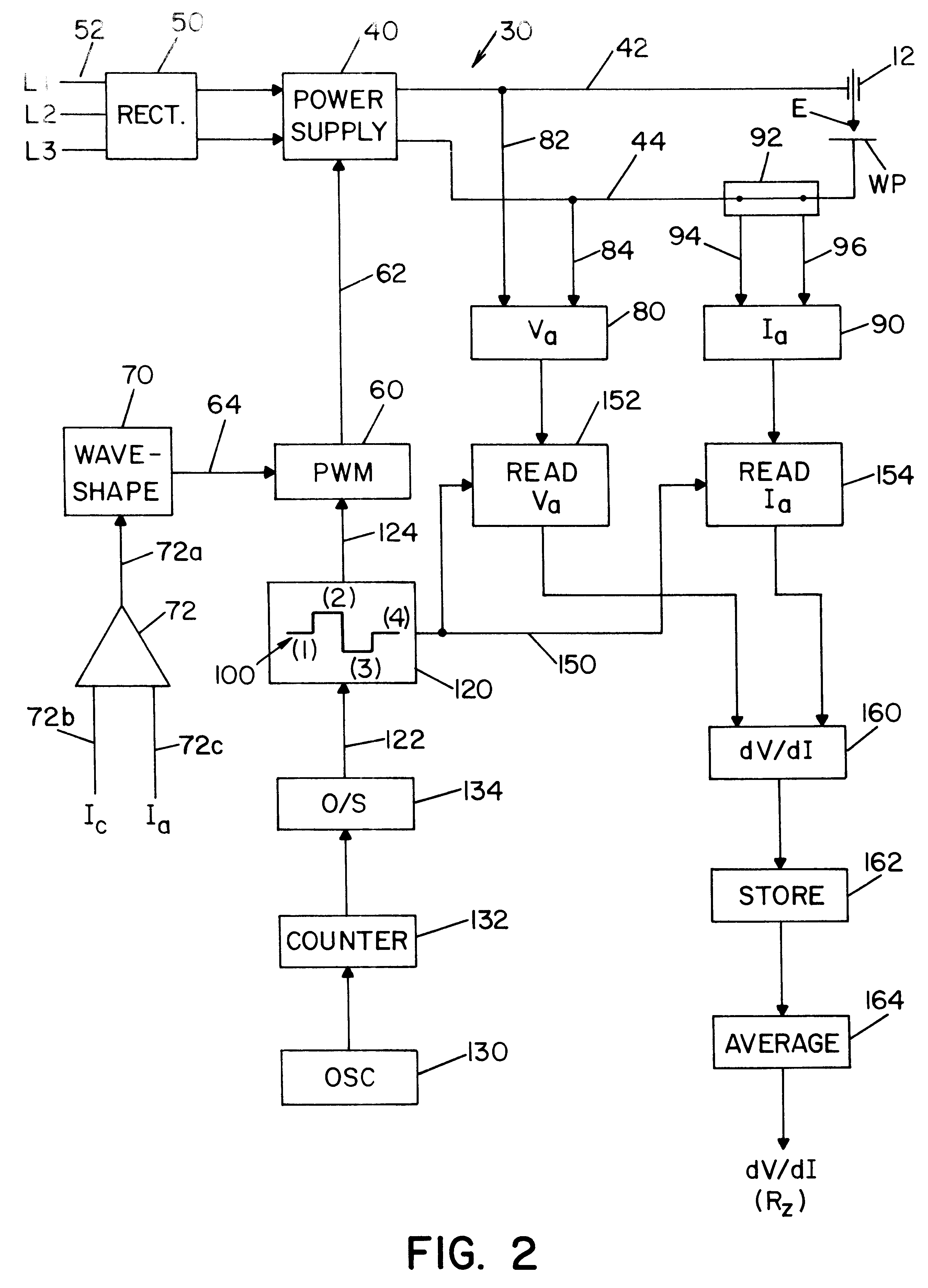
In accordance with another aspect of the present invention, the derivative forming the primary feature of the invention is obtained by a small dither of the welding current. A dither pattern is applied to the welding current to determine the "incremental impedance" or "incremental resistance" R.sub.z of the welding circuit. Before the dither, the voltage and current are sensed. The dither pattern then increases current and waits for a time delay. This delay removes distortion caused by inductive reactance. The voltage and current is again measured and recorded. By subtracting the voltage readings and subtracting the current readings the derivative of voltage to current is obtained by dividing the voltage difference by the current difference. By using a derivative of the relationship between voltage and current, a high resolution circuit is used because the difference in current is quite small and the resulting derivative value is in the general range of 0.005-0.075 ohms. The difference in voltage is also quite small and is in the general range of 0.15 to 2.0 volts. Consequently, high resolution is used for the sensing. However, absolute accuracy is not critical since the incremental impedance value is a derivative measurement. Thus, resolution is required, but accuracy of the data values is not critical. Since large values of the current dither will also affect arc length, the dither is limited to a small percentage of the welding current to avoid influencing the arc length. In practice, the dither of the current is less than about 10% and generally less than about 5% of the current being used in the welding process. Although the derivative can be obtained by merely increasing the current to measure the voltage and current before and after the increase, in the preferred embodiment of the invention, the current is increased preparatory to a second voltage and current measurement. Thereafter, the current is decreased below the welding current to give a third measurement. Following this measurement, the current is raised back to the welding current for a fourth measurement. Consequently, there are four readings of voltage and current to provide three separate difference values gathered for one current dither pattern. The second difference value is based upon substantially larger current variation than the first or the last current differences caused by the dither pattern. By obtaining three sets of differences, dividing them to give derivatives and then averaging them by dividing the sum of the derivatives by three, a better representation of the actual derivative value or control signal is obtained.
In the multiple data gathering dither pattern of the present invention the current is shifted positive and then negative. This helps to balance the small, instantaneous arc length changes caused by the dither. Equal positive and negative transitions of shifts balance the power source output so that the melt off rate is not affected by the dithers of the current. The second current shift in the dither pattern is generally twice the first current transition. This doubles the gathered data values to provide better resolution. By using three consecutive derivatives, a more consistent control signal is generated. In practice, the voltage and current measurements are taken about each 10 milliseconds. Such timing does not alter most wave form control wave forms. The dV / dI data is extracted for the purpose of estimating electrode stickout and arc length.
Yet another object of the present invention is the provision of a method and system, as defined above, which method and system can be used to accurately obtain a control function for maintaining arc length or other parameters.

Problems solved by technology

When the voltage is held constant, changes in the CTWD cause current changes as well as other process variations; therefore, control arrangements using the volts / ampere characteristics curve for the process have inherent limitations.
Attempts to regulate the DC GMAW welding process based upon electrode stickout or CTWD have presented difficulties, since these parameters are difficult to determine on a real time basis.

Method used


Image

  • Method of controlling arc welding processes and welder using same
  • Method of controlling arc welding processes and welder using same
  • Method of controlling arc welding processes and welder using same

Examples


Embodiment Construction

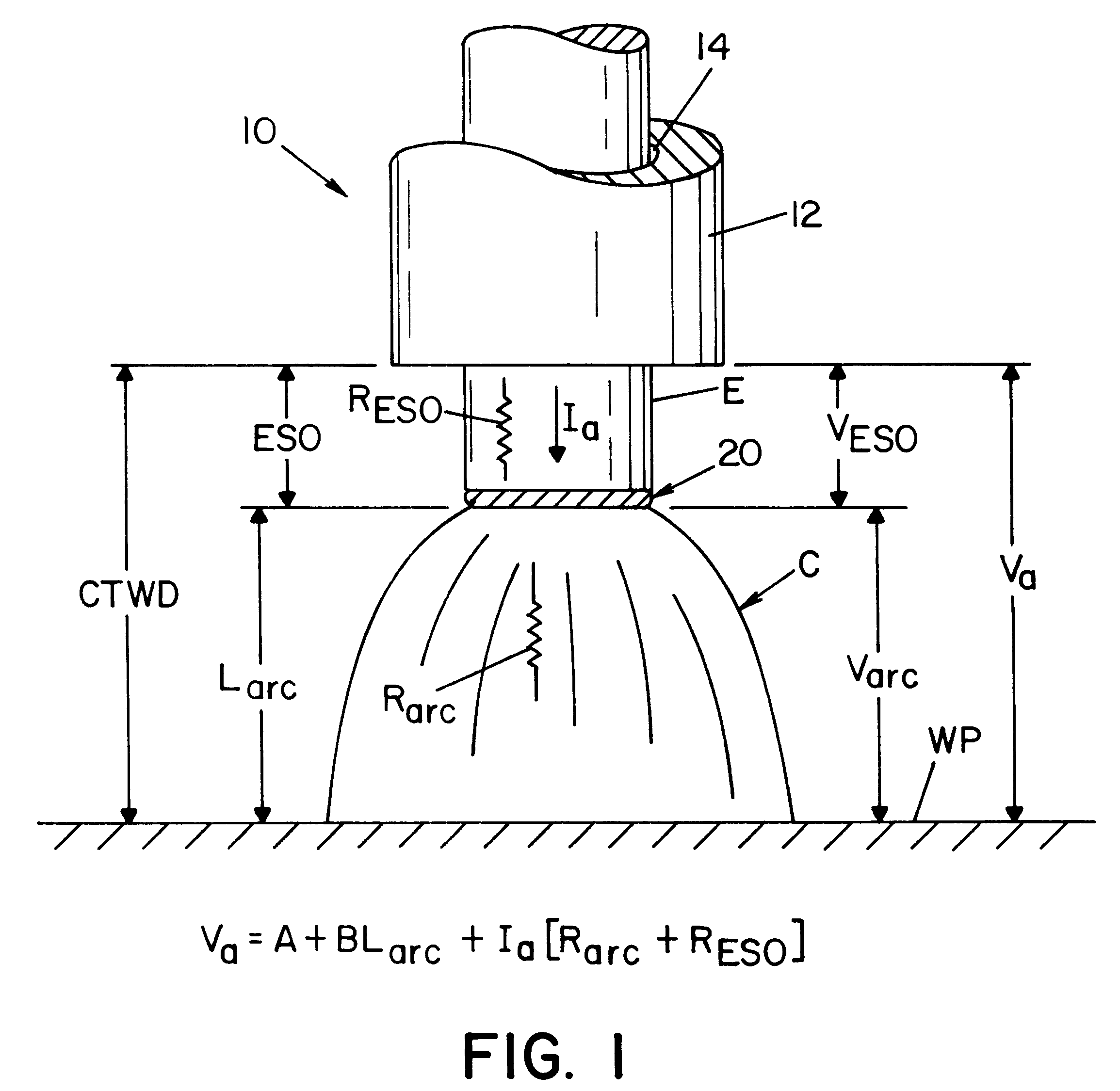
Referring now to the drawings wherein the showings are for the purpose of illustrating the preferred embodiment of the invention only and not for the purpose of limiting same, FIG. 1 illustrates an electric arc welding process 10 wherein contact tip 12 has an opening 14 through which is advanced steel electrode E toward a ferrous workpiece WP. The welding metals are steel in the preferred embodiment; however, other metals, such as aluminum, have been welded using the invention. Between the end of the electrode and the workpiece is an electric arc C. In practice, electric energy is directed by contact tip 12 through electrode E to create arc C to melt the end of the electrode and causes transfer of metal either by spray, short circuit or globular transfer. In the welding process, the distance between tip 12 and workpiece WP is CTWD, which is the system of electrode stickout ESO and the arc length L.sub.arc. Welding voltage V.sub.arc is divided into voltage across electrode V.sub.ESO ...


PUM

PropertyMeasurementUnit
Fractionaaaaaaaaaa
Timeaaaaaaaaaa
Lengthaaaaaaaaaa

Abstract

A method of generating a real time control signal for use in an electric arc welding process having welding voltage and welding current, said method comprising: measuring the welding voltage and welding current at a first time, momentarily changing either the welding voltage or welding current by less than about 10%, then measuring the welding voltage and the welding current after the change at a second time, determining the welding voltage difference between the first time and the second time, determining the welding current difference between the first time and the second time, producing a derivative value representing the desired control signal by dividing the welding voltage difference between the first and second times by the welding current difference between the first and second times and generating the control signal by the derivative value.

Description

The present invention relates to the art of electric arc welding and more particularly to a method of controlling arc welding processes using a unique control parameter and a welder having a controller for developing and using such unique parameter.BACKGROUND OF INVENTIONElectric arc welding is a complex electrical phenomenon having many process control variables affecting the quality of the weld, whether using spray transfer, pulse transfer, DC GMAW welding or AC welding. In constant voltage welding processes, the welding process is normally controlled by the welding current I.sub.a. When the voltage is held constant, changes in the CTWD cause current changes as well as other process variations; therefore, control arrangements using the volts / ampere characteristics curve for the process have inherent limitations. The contact tip to work distance CTWD has a major influence on current since the current increases as the CTWD decreases and vice versa. Attempts to regulate the DC GMAW w...

Claims


Application Information

Patent Timeline
IPC IPC(8): B23K9/095B23K9/10B23K9/073B23K9/09
CPCB23K9/0953B23K9/1043B23K9/095
Inventor BLANKENSHIP, GEORGE D.
Owner LINCOLN GLOBAL INC
Learn More