Laser irradiation apparatus

Inactive Publication Date: 2001-06-19
SEMICON ENERGY LAB CO LTD
View PDF15 Cites 54 Cited by
  • Summary
  • Abstract
  • Description
  • Claims
  • Application Information

AI Technical Summary

Benefits of technology

The above discussion also applies in completely the same manner even if the term "beam movement direction" is replaced by another term "direction perpendicular to the longitudinal direction, i.e., the shorter-axis direction (of a linear beam)." The direction of the multi-cylindrical lens 4 need not be perpendicular to the beam movement direction; it is sufficient that

Problems solved by technology

This type of configuration has

Method used


Image

  • Laser irradiation apparatus
  • Laser irradiation apparatus
  • Laser irradiation apparatus

Examples


embodiment 1

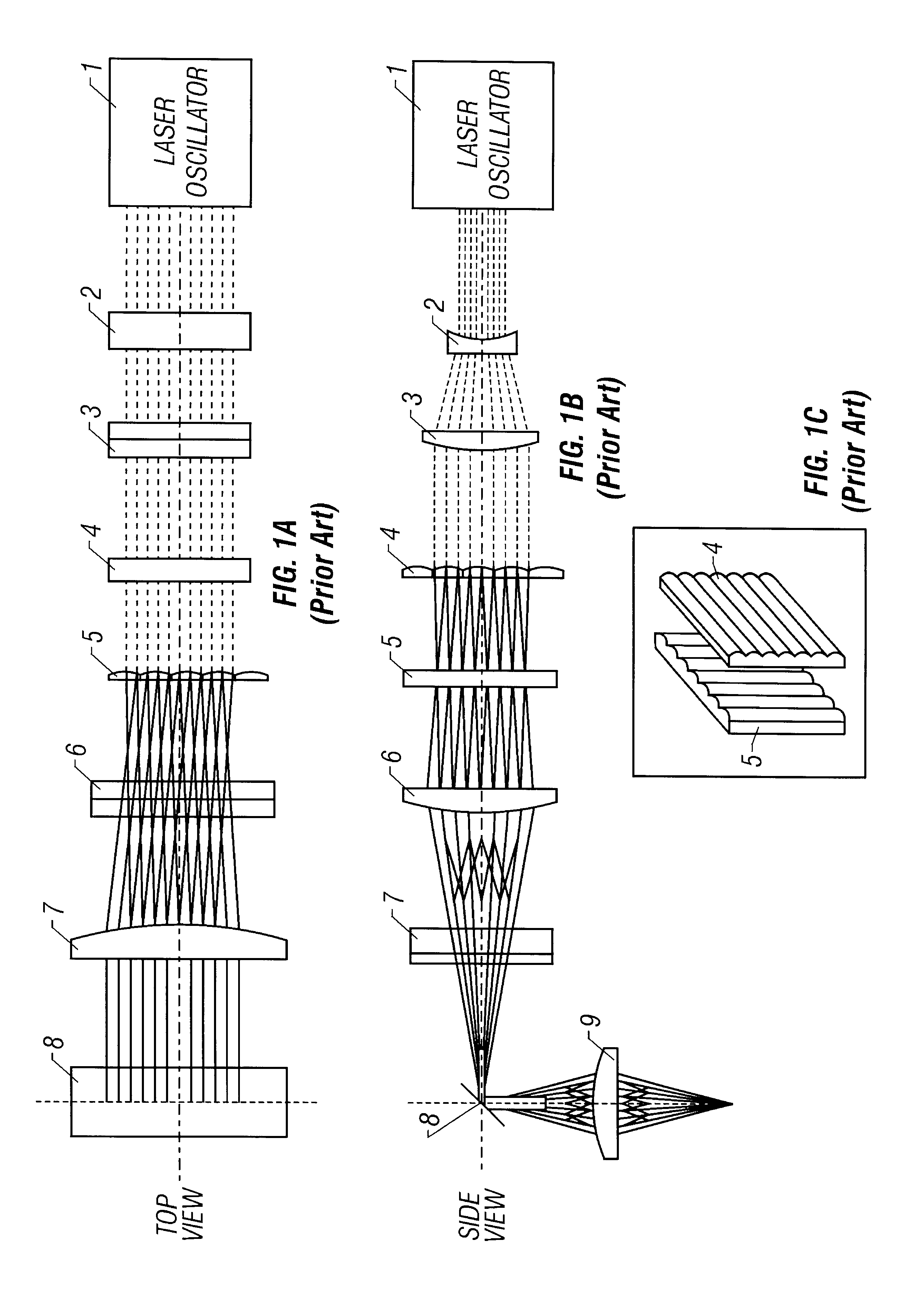
An optical system according to this embodiment will be described below. The basic configuration of a laser irradiation apparatus according to this embodiment is the same as that shown in FIG. 1 except an angle around the optical axis of the multi-cylindrical lenses of the homogenizer. An original beam before entering the homogenizer has a rectangular shape of 6 cm.times.5 cm. The following description will be concentrated on the homogenizer.

In the configuration of this embodiment, the multi-cylindrical lens 5 is composed of 12 cylindrical lenses each being 5 mm in width and divides incident laser light into about 10 parts.

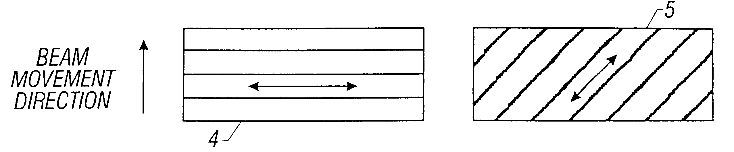
In this embodiment, a linear laser beam that is finally applied has a longitudinal length of 12 cm. The direction of the multi-cylindrical lens 5 is set so as to form 45.degree. with the beam movement direction. On the other hand, the direction of the multi-cylindrical lens 4 is set perpendicular to the beam movement direction (see FIG. 9A).

The width of a beam that...

embodiment 2

FIG. 10 schematically shows a configuration according to this embodiment.

In this embodiment, rectangular laser light 801 output from a laser oscillator (not shown) is passed through or reflected by multi-cylindrical lenses 802 and 803, cylindrical lenses 804 and 805, a mirror 806, and a cylindrical lens 807, whereby it is shaped into linear laser light, which is finally applied to an irradiation surface.

The configuration of FIG. 10 has a feature that the two multi-cylindrical lenses 802 and 803 are inclined by 45.degree. from the beam movement direction and the longitudinal direction of the beam. (That is, the multi-cylindrical lenses 802 and 803 are located orthogonally each other.)

Although two multi-cylindrical lenses are used in this embodiment, three or more multi-cylindrical lenses may be used.

As described above, the invention provides a technique capable of performing uniform annealing over a large area in laser irradiation processes that are used for manufacture of semiconduc...


PUM

PropertyMeasurementUnit
Angleaaaaaaaaaa
Light intensityaaaaaaaaaa
Semiconductor propertiesaaaaaaaaaa

Abstract

An apparatus for irradiating an irradiation surface with a laser light having a linear or rectangular shape. A homogenizer operates on the principle that variations in the light intensity profile of an original beam as emitted from a laser device are dispersed by passing the original beam through two multi-cylindrical lenses. The directions of the respective multi-cylindrical lenses are set so as not to be parallel with the beam movement direction. Thus, an uniformity of annealing by irradiating with a laser light is improved.

Description

BACKGROUND OF THE INVENTION1. Field of the InventionThe present invention relates to an apparatus to be used for an annealing or exposure process including laser light irradiation. For example, the invention relates to an apparatus that provides a uniform irradiation effect in a laser annealing apparatus in which irradiation with a large-area beam is performed. This type of laser annealing apparatus is used for semiconductor manufacturing processes.2. Description of the Related ArtThe technique of crystallizing an amorphous silicon film by irradiation with laser light is known. Further, the technique of irradiating a silicon film that has been damaged by implantation of impurity ions to recover its crystallinity and to activate implanted impurity ions is also known. They are called laser annealing techniques.A typical example of the latter technique is a technique for annealing the source and drain regions of a thin-film transistor. In this technique, the source and drain regions ar...

Claims


Application Information

Patent Timeline
IPC IPC(8): B23K26/06B23K26/073G02B27/09G02B3/00G03F7/20H01L21/027H01L21/268
CPCB23K26/0604B23K26/0732G02B3/005G02B3/0062G02B3/06G02B27/09G02B27/0905G02B27/0961G02B27/0966
Inventor YAMAZAKI, SHUNPEITANAKA, KOICHIROKUSUMOTO, NAOTO
Owner SEMICON ENERGY LAB CO LTD
Why Eureka
Try Eureka