Barrier valve with pressure limiting function in particular for slip-controlled hydraulic brake systems of motor vehicles

Inactive Publication Date: 2001-06-26
ROBERT BOSCH GMBH
View PDF20 Cites 6 Cited by
  • Summary
  • Abstract
  • Description
  • Claims
  • Application Information

AI Technical Summary

Benefits of technology

The barrier valve according to the invention has the advantage over the prior art that because of the stroke limitation of the tappet in the pressure-limiting opening of the seat valve, an "excess stroke" of the tappet is avoided, and upon closure of the seat valve out of the pressure limiting function, the tappet is moved without vibration into the closing position. This might be ascribed to the fact that the stroke limitation of the tappet results in largely stable flow conditions at the closing body, which prevents longitudinal vibration from occurring when the hydraulic forces are lessening.By the provisions recited, advantageous refinements of and improvements to the barrier valve defined herein are attained.In terms of the function and structural design of the barrier valve, the provisions recited herein are highly advantageous, because of their simple design, their manufacture at favorable cost, and the assembly of the affected individual parts of the valve.Since the tappet, with the interposition of the support body, cooperates functionally with the compression spring located inside the armature, the embodiment of the support body herein is advantageous, because as a result the tappet can be provided with a flat end face, which makes it less expensive to produce.With the adaptation of the components of the barrier valve as recited herein, teaching is provided with which the above-described mode of operation for pressure limitation is assured.

Problems solved by technology

This causes irritating flow noises.

Method used


Image

  • Barrier valve with pressure limiting function in particular for slip-controlled hydraulic brake systems of motor vehicles
  • Barrier valve with pressure limiting function in particular for slip-controlled hydraulic brake systems of motor vehicles
  • Barrier valve with pressure limiting function in particular for slip-controlled hydraulic brake systems of motor vehicles

Examples


Embodiment Construction

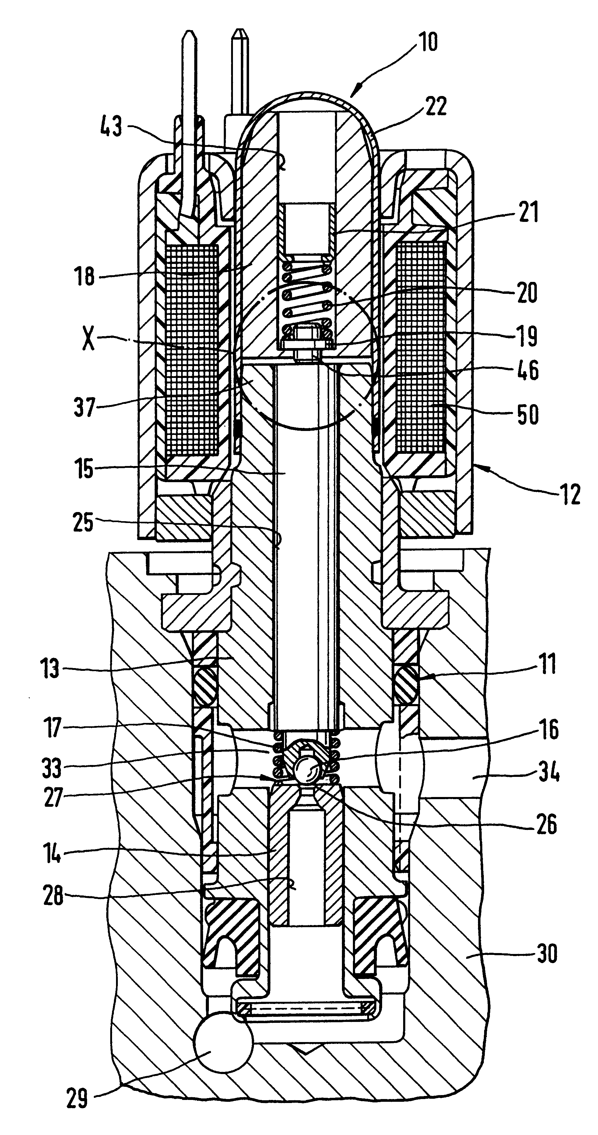
A barrier valve with a pressure limiting function, shown at 10 in FIG. 1, comprises two component groups, a hydraulic group 11 and a magnet group 12. The hydraulic group 11 has essentially the following components: a valve housing 13 with a valve body 14, a tappet 15 with a closing body 16, a restoring spring 17, an armature 18 with a support body 19, a compression spring 20, and a press-fitted bush 21 and an armature guide sleeve 22.

The valve housing 13 has a continuous longitudinal bore 25, into which the valve body 14 is press-fitted, remote from the armature. The valve body 14 has a hollow-conical valve seat 26 associated with the closing body 16 of the armature 18. The closing body 16 and the valve seat 26 together form a seat valve 27 of the barrier valve 10, the seat valve being open when there is no electric current. Through a stepped bore 28 of the valve body 14, the valve seat 26 communicates with a pressure fluid line 29 of a valve block 30, in which the hydraulic group 1...


PUM


Abstract

A barrier valve including an armature, longitudinally movable toward a pole core by excitation of an electrical winding. A prestressed compression spring in a longitudinal bore of the armature, as well as a support body, loaded by the compression spring, that is braced on a shoulder of the bore. The barrier valve furthermore has a tappet, which engages the support body and is movable relative to the armature and carries a closing body of a seat valve. When the winding is excited, the closing body is movable, overcoming the valve stroke, toward a valve seat of the seat valve. When the winding is excited, the closing body can be lifted from the valve seat by hydraulic forces acting on the closing body toward the valve seat, counter to the spring force of the compression spring in the armature. The stroke of the tappet relative to the armature engaging the pole core is limited to an amount less than the valve stroke. The barrier valve can be used in slip-controlled hydraulic brake systems and is distinguished by low noise when the pressure limiting function becomes operative.

Description

PRIOR ARTThe invention is based on a barrier valve for slip-controlled hydraulic brake systems of motor vehicles.A barrier valve of this type for hydraulic motor vehicle brake systems is already known (German Patent DE 40 41 506 C2), in which the tappet, from the closing position of the seat valve, plunges counter to the force of the compression spring into the armature if the response pressure for making the pressure limiting function operative is exceeded. If the hydraulic forces acting on the closing body of the seat valve decrease, then the tappet moves together with the closing body in the direction of the valve seat, because of the spring force of the compression spring in the armature, and is exposed to more or less sharply decreasing longitudinal vibrations in the flow cross section of the seat valve before closure of the seat valve occurs. This causes irritating flow noises.ADVANTAGES OF THE INVENTIONThe barrier valve according to the invention has the advantage over the pr...

Claims


Application Information

Patent Timeline
IPC IPC(8): B60T8/36F15B11/00F15B13/044F15B13/00F15B11/028B60T13/66F16K31/06
CPCB60T8/365F15B11/028F16K31/0655F16K17/048F15B13/044Y10S303/901
Inventor SCHNALZGER, GUENTHERZIMMERMANN, PETERMUELLER, ROBERT
Owner ROBERT BOSCH GMBH
Why Eureka
Try Eureka