Brushless, separately-excited, variable-speed motor and AC generator/alternator with solenoid-wound, biphase AC rotor

a variable speed motor and solenoid-wound technology, applied in the direction of magnetic circuit rotating parts, electric generator control, magnetic circuit shape/form/construction, etc., can solve the problems of increasing the cost of stator and rotor complexity, significantly more complex electromechanical machines, and increasing the cost of induction machines

Inactive Publication Date: 2001-06-26
MILDICE JAMES W +2
View PDF21 Cites 52 Cited by
  • Summary
  • Abstract
  • Description
  • Claims
  • Application Information

AI Technical Summary

Problems solved by technology

Such systems are not universally applied because of losses in the controller and the unavailability of controllers for large systems, since these controllers must process all of the power required by the system load.
This type of electromechanical machine is significantly more complex and expensive than an equivalent induction machine.
The improvements to such machines suggested in the Lauw patents eliminate the slip rings and brushes, but at the cost of still more stator and rotor complexity.

Method used


Image

  • Brushless, separately-excited, variable-speed motor and AC generator/alternator with solenoid-wound, biphase AC rotor
  • Brushless, separately-excited, variable-speed motor and AC generator/alternator with solenoid-wound, biphase AC rotor
  • Brushless, separately-excited, variable-speed motor and AC generator/alternator with solenoid-wound, biphase AC rotor

Examples


Embodiment Construction

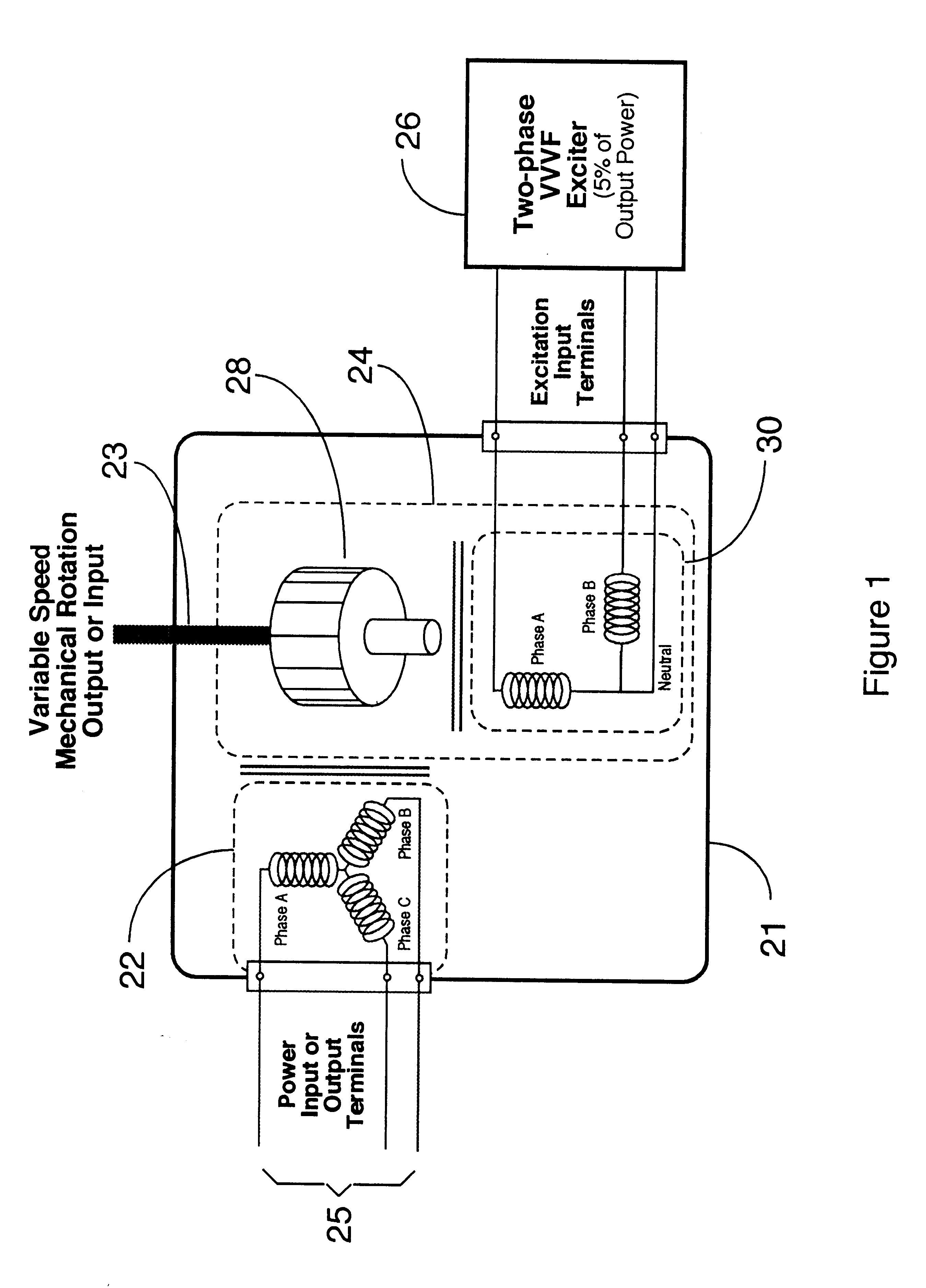
As illustrated in FIG. 1, a machine 21 of the present invention includes a three-phase (or other conventional design) stator 22 and a two-phase (biphase) AC rotor 24. As indicated by the duality shown in FIG. 1, the machine can operate as a motor or as an AC generator or alternator. As a motor, power is supplied to the stator terminals 25, and the shaft 23 provides the variable-speed, variable-torque, mechanical rotation output. As a generator or alternator, the shaft 23 is driven by a mechanical source (such as an engine) and variable voltage, variable-frequency power is supplied from the stator windings 25 to electrical loads.

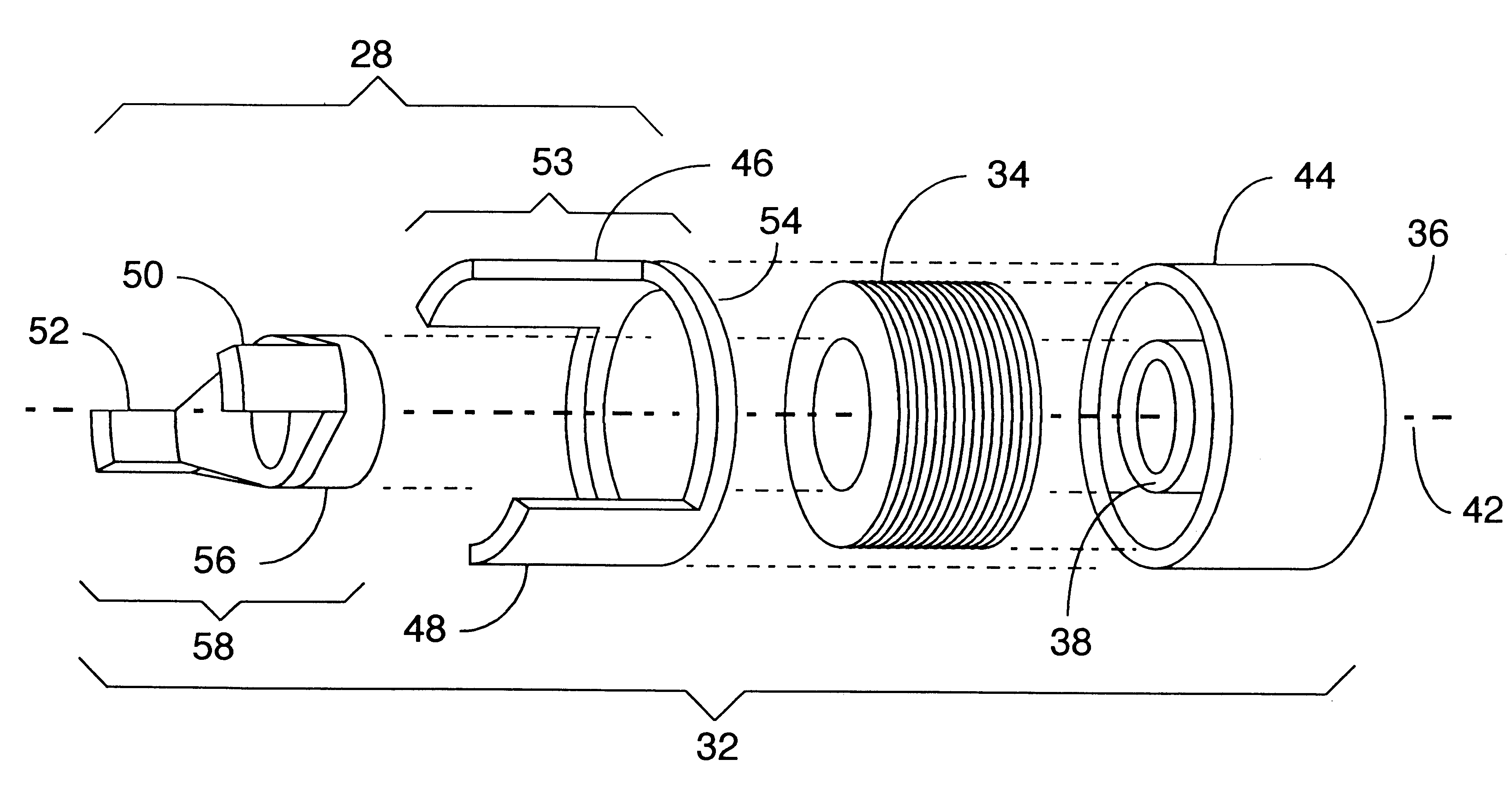
In a motor or alternator system, the machine rotor is supplied by a two-phase, variable-voltage, variable-frequency exciter 26. In typical operation, the exciter only needs to control about 5% of the total system throughput. The rotating pole piece assembly 28 rotates with respect to stator 22 and is magnetically coupled to the two-phase rotor excitation coil...


PUM


Abstract

A rotating electrical machine includes a two-phase rotor having two non-rotating solenoid-wound rotor coil assemblies and two interleaved pole assemblies. Each pole assembly is magnetically coupled to its respective coil assembly and rotates together with the machine shaft. Each pole assembly has four or more elongated pole pieces, two of which couple with one pole of a coil assembly and two of which couple with the other pole of that coil assembly. An exciter circuit independently controls the power variables provided to the rotor with respect to the stator to provide a variable-speed, variable-frequency (VSVF) motor system or VSVF generator system. The exciter energizes the solenoid-wound rotor coils with biphase AC electrical excitation, to produce a radial, rotating magnetic field at the pole pieces.

Description

1. Field of the InventionThis invention relates generally to electromagnetic machines and, more specifically, to a variable-speed, variable-frequency synchronous machine and system that can operate as a motor or generator / alternator, wherein the primary input and output parameters, such as rotational speed, frequency, and voltage, are fully decoupled from one another.2. Description of the Related ArtAs illustrated in FIG. 2a, many conventional electronically-controlled, variable-speed, alternating current (AC) motor drive systems include a conventional electromechanical machine, typically an induction motor 10. Such systems are taught by Knox, U.S. Pat. No. 4,491,778, and many others. On a first order basis, motor speed is proportional to its power input frequency. Motor 10 is made to run at a commanded speed, different from what is allowed by the prime power source, by interposing a variable-voltage, variable-frequency (VVVF) controller / power processor 12 between it and its power s...

Claims


Application Information

Patent Timeline
Patent Type & Authority Patents(United States)
IPC IPC(8): H02P25/02H02K19/12H02K19/26H02K19/02H02K19/16H02P7/285H02P7/18H02P9/30H02P9/14
CPCH02K19/12H02K19/26H02P9/30H02P25/021H02P7/2855H02P2101/30H02P25/024
Inventor MILDICE, JAMES W.HOLLOPETER, JAMES E.WESTERGREN, DONALD M.
Owner MILDICE JAMES W
Why Eureka
Try Eureka