Method for identifying a fast speed mobile station, and a base station

a mobile station and fast speed technology, applied in the field of fast speed mobile station identification and base station identification, can solve the problems of speed mobile station as fast speed mobile station may unnecessarily overload the larger radio cell, the quality of connection deteriorates, and the speed mobile station may not be reliably identified

a mobile station and fast speed technology, applied in the field of fast speed mobile station identification and base station identification, can solve the problems of speed mobile station as fast speed mobile station may unnecessarily overload the larger radio cell, the quality of connection deteriorates, and the speed mobile station may not be reliably identified

US6259919B1Inactive Publication Date: 2001-07-10NOKIA TECHNOLOGLES OY

Image

  • Method for identifying a fast speed mobile station, and a base station
  • Method for identifying a fast speed mobile station, and a base station
  • Method for identifying a fast speed mobile station, and a base station

Examples


Embodiment Construction

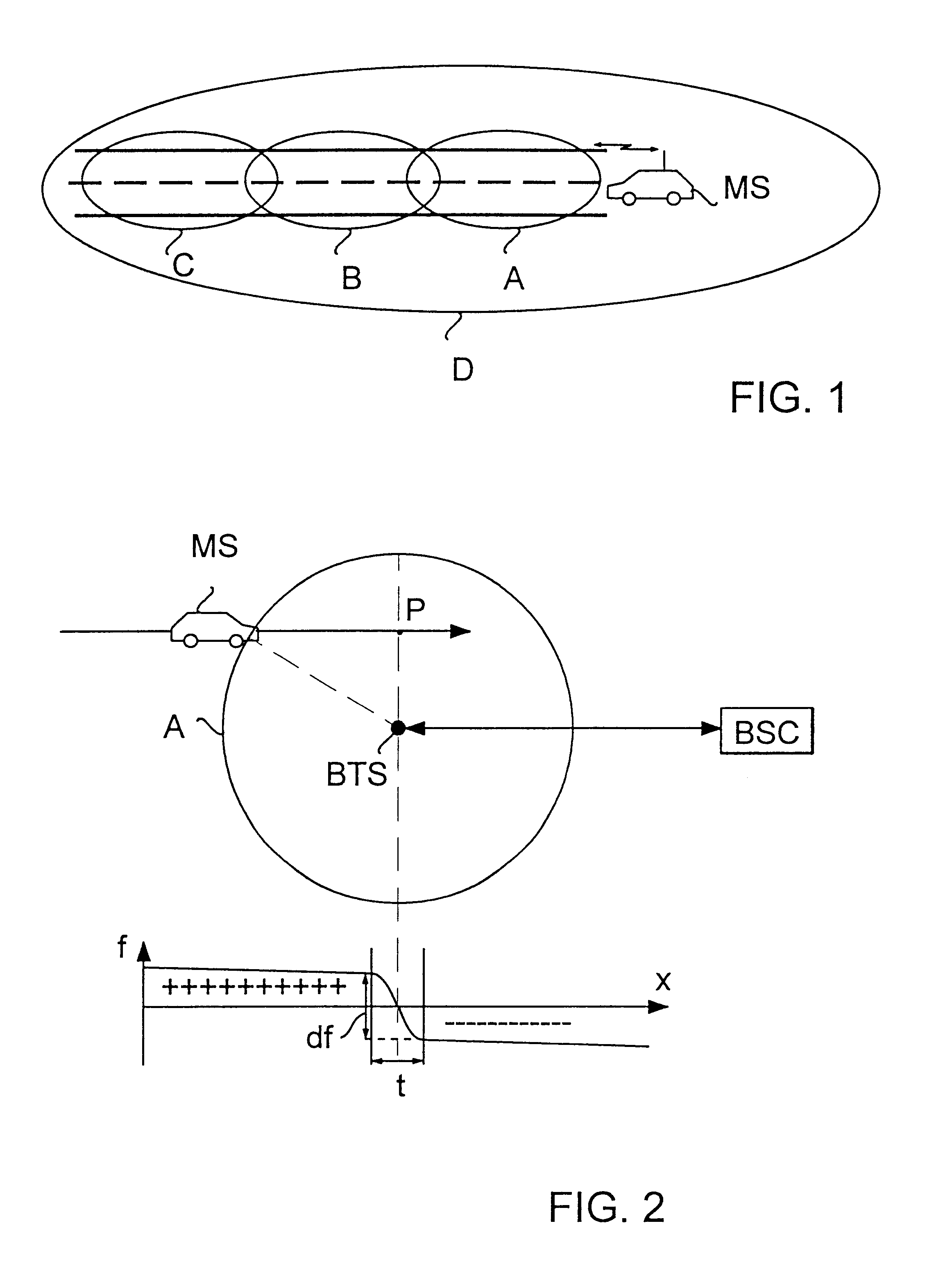
FIG. 1 illustrates the motion of a mobile station in a cellular radio system. The part of a cellular radio system illustrated in FIG. 1 may be, for example, the GSM system (Groupe Special Mobile). Microcells A, B and C are arranged along a road and, in addition, the section of the road is served by a larger cell D.

When the mobile station MS in the car shown in FIG. 1 moves along the road, it is at first served by the base station of cell A. Thereafter a handover takes place to the base station of cell B and finally to the base station of cell C. If the mobile station is a fast speed mobile station (FSMS), these handovers take place at very short intervals, which loads the network management resources unnecessarily, and moreover, the quality of the connection deteriorates. In the case of FIG. 1, it would therefore be more advantageous to hand the mobile station MS over to the larger cell D, if it is identified as a fast speed mobile station.

FIG. 2 illustrates the frequency error dete...


PUM


Abstract

A method for identifying a fast speed mobile station (MS) in a radio system, said method comprising measuring the frequency error of radio signals received from a mobile station. In order for a fast speed mobile station to be more reliably identified than before, the method comprises calculating the change (df) in BSC the frequency error from a time interval (t) of predetermined length, and identifying the mobile station as a fast speed mobile station if the change (df) in the calculated frequency error exceeds a predetermined limit value.

Description

This application is the national phase of international application PCT / F196 / 00352 filed Jun. 13, 1996 which designated the U.S.1. Field of the InventionThe invention relates to a method for identifying a fast speed mobile station in a radio system, said method comprising measuring the frequency error of radio signals received from a mobile station.The invention further relates to a base station of a radio system, said base station comprising receiver means for receiving signals transmitted by a radio unit, and measuring means for measuring the frequency error of the received signals.2. Description of Related ArtThe invention relates particularly to the problem created in cellular radio systems when a fast speed mobile station (FSMS) roams in a microcellular network and thus changes base station frequently. Changes of base station load the network management resources significantly and, moreover, the quality of the connection deteriorates. In a situation of this kind it is preferab...

Claims


Application Information

Patent Timeline
10 Jul 2001
Publication
US6259919B1
IPC
G01S11/10; G01S11/00; H04Q7/38; G01S11/02; H04B7/26; H04W36/32
CPC
G01S11/10; H04W36/32; H04W36/324
Inventors
SUONVIERI, JUKKA; INKINEN, KULLERVO