Cold tandem rolling method and cold tandem rolling mill

a technology of cold tandem rolling and tandem rolling mill, which is applied in the direction of rolling mill control devices, manufacturing tools, profile control devices, etc., can solve the problems of increasing production costs, affecting the productivity of the product, and affecting the accuracy of sheet thickness temporarily, so as to prevent scratches without deteriorating productivity, raising production costs, and improving accuracy

Inactive Publication Date: 2001-08-07
NIPPON STEEL CORP
View PDF14 Cites 14 Cited by
  • Summary
  • Abstract
  • Description
  • Claims
  • Application Information

AI Technical Summary

Benefits of technology

As described above, the effect provided by the conventional tandem cold rolling method is limited. The reasons are described as follows. According to the method by which the occurrence of scratches is prevented without deteriorating the productivity and raising the production cost, there is a possibility that the accuracy of sheet thickness is temporarily deteriorated in the case of changing the reduction schedule. According to the method by which the tension given to the sheet is changed, since the rolling pressure is decreased and the generation of heat caused by friction is decreased by increasing the tension, it is possible to prevent the occurrence of heat scratches. However, when the tension is increased in order to enhance the effect of prevention of heat scratches, the sheet to be rolled tends to break. According to the tandem cold rolling mill of the prior art, heat scrat

Problems solved by technology

As described above, the effect provided by the conventional tandem cold rolling method is limited.
According to the method by which the occurrence of scratches is prevented without deteriorating the productivity and raising the production cost, there is a possibility that the accuracy of sheet thickness is temporarily deteriorated in the case of changing the reduction schedule.
However, when the tension is increased in order to enhance the effect of prevention of heat scratches, the sheet to be rolled tends to break.
According to the tandem cold rolling mill of the prior art, heat scratches tend to occur in the cold rolling stands in the latter stage, and further it is im

Method used


Image

  • Cold tandem rolling method and cold tandem rolling mill
  • Cold tandem rolling method and cold tandem rolling mill
  • Cold tandem rolling method and cold tandem rolling mill

Examples


example 1

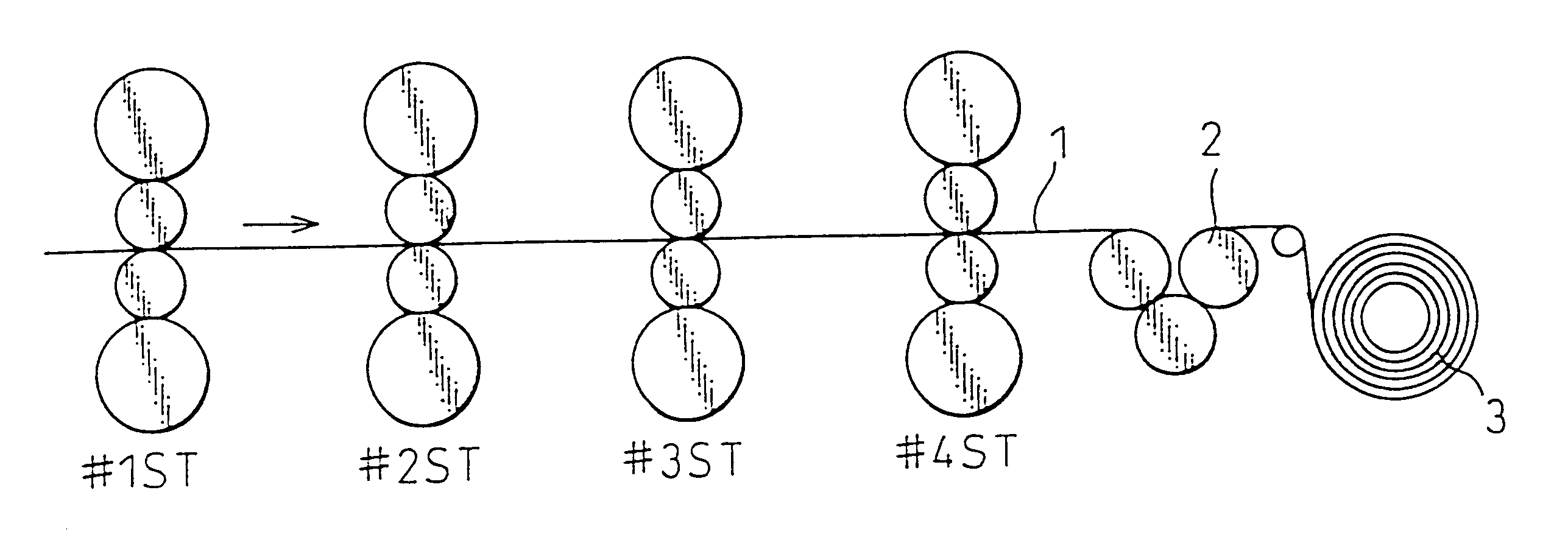
FIG. 5 is an overall arrangement view of the tandem cold rolling mill to which the present invention is applied. As illustrated in FIG. 5, the tandem cold rolling mill is composed of 4-high cold rolling stands, the number of which is 4. The rolling sheet (1) is rolled in each rolling stand and passes through the bridle rollers (2). Then the rolling sheet (1) is wound by the coiler (3). The rolling conditions are described as follows. In this connection, in the case where bridle rollers are provided and an intensity of rolling tension is 20 kgf / mm.sup.2, an intensity of tension between the delivery side of the rolling mill and the bridle rollers is 30 kgf / mm.sup.2, and an intensity of tension between the delivery side of bridle rollers and the coiler is 10 kgf / mm.sup.2. In the case where the bridle rollers are provided and an intensity of rolling tension is 0 kgf / mm.sup.2, an intensity of tension between the delivery side of the rolling mill and the bridle rollers is 30 kgf / mm.sup.2,...

example 2

In this example, the same tandem cold rolling mill, which was a 4-stand type 4-high tandem cold rolling mill, as that shown in FIG. 7 was used. The following are the rolling conditions of the fourth rolling stand at which heat scratches tend to occur on the surface of a rolled sheet.

Diameter of work roll (D): .PHI.480 mm

Speed of work roll (V.sub.R): 300 m / min

Tension on entry side (.sigma..sub.bs): 10 kgf / mm.sup.2

Tension on delivery side (.sigma..sub.fs): 5 kgf / mm.sup.2

Sheet thickness on entry side (H): 0.84 mm

Sheet thickness on delivery side (h): 0.60 mm

Sheet width (W): 988 mm

Thickness of material to be rolled (H.sub.s): 3.2 mm

Material: low carbon steel .sigma..sub.y =67(.epsilon.+0.03).sup.0.2 kgf / mm.sup.2

Lubrication of rolling: 2% emulsion of beef tallow (60.degree. C.)

In the process of rolling, when a large number of coils of the same size are rolled under the same rolling condition, the average temperature of the work roll is raised, and the sheet temperature on the delivery sid...

example 3

In order to make investigation into the effect of the present invention, the inventors made experiments using the same rolling mill and the same rolling conditions as those of Example 2. Conditions to restrict the tension were determined as follows. The entry side tension .sigma..sub.b =.sigma..sub.bs +.alpha., and the delivery side tension .sigma..sub.f =.sigma..sub.fs +.alpha. / 10. The maximum value .sigma..sub.bmax of tension on the entry side at which the sheet was not broken was set at 15 kgf / mm2, and the maximum value .sigma..sub.fmax of tension on the delivery side at which the sheet was not broken was set at 10 kgf / mm.sup.2.

FIGS. 9(a) and 9(b) are graphs showing the effect of the present invention. FIG. 9(a) shows a relation between the number of rolled coils and the tension on the entry side of the fourth rolling stand, and FIG. 9(b) shows a relation between the number of rolled coils and the work roller speed of the fourth rolling stand. Mark .quadrature. in FIGS. 9(a) and ...


PUM

PropertyMeasurementUnit
Fractionaaaaaaaaaa
Fractionaaaaaaaaaa
Fractionaaaaaaaaaa

Abstract

The present invention is to provide a tandem cold rolling method conducted by a tandem cold rolling mill, the number of rolling stands of which is not less than 4, wherein a rolling tension, the intensity of which is not lower than 30%, preferably not lower than 40% of the deformation resistance of material to be rolled, is given at least by the final rolling stand. The present invention is also to provide a tandem cold rolling mill satisfying the inequality of JC>=(0.375{overscore (h)}+0.275)JM, wherein the average thickness of a product sheet on the delivery side of the final rolling mill is {overscore (h)}, and an output of one coiler arranged on the delivery side of the tandem cold rolling mill, or a sum of an output of one coiler on the delivery side and an output of the bridle roller on the delivery side is JC, and an output of the main motor of the final rolling stand of the tandem cold rolling mill is JM.

Description

The present invention relates to a tandem cold rolling method and a tandem cold rolling mill thereof, the number of cold rolling stands of which is not less than 4, by which the occurrence of heat scratches is prevented and the productivity is enhanced so that the production cost can be decreased.When the work roll speed is increased or the ratio of reduction is increased in a tandem cold rolling mill, heat scratches are caused on the surface of a cold-rolled sheet. A heat scratch is defined as a defect of seizing caused by metallic contact of a work roll with a sheet to be rolled when the temperature of an interface between the work roll and the sheet to be rolled is raised in a rolling bite and an oil film is broken.When heat scratches occur on the surface of a product, the product becomes defective, and the product yield is lowered. Further, the work rolls of a cold rolling stand in which the heat scratches occur must be changed. Accordingly, the productivity of the cold rolling ...

Claims


Application Information

Patent Timeline
IPC IPC(8): B21B37/48B21B37/54B21B1/28B21B1/24
CPCB21B37/54B21B1/28
Inventor SHIRAISHI, TOSHIYUKIOGAWA, SHIGERUHAMAUZU, SHYUICHIISHII, ATSUSHI
Owner NIPPON STEEL CORP
Why Eureka
Try Eureka