Aircraft with a double-T tail assembly

a technology of rudder and tail section, which is applied in the direction of wings, automatic actuation, aircraft floors, etc., can solve the problems of difficult to provide double rudder assemblies that extend difficult to use on commercial aircraft, and the possibility of extending double rudder assemblies from the tail section of the fuselage is hardly feasible in commercial aircraft. , to achieve the effect of reducing the cross-section of the tail section, reducing the size of th

Inactive Publication Date: 2001-08-14
DAIMLER CHRYSLER AEROSPACE AIRBUS
View PDF11 Cites 37 Cited by
  • Summary
  • Abstract
  • Description
  • Claims
  • Application Information

AI Technical Summary

Benefits of technology

In the aircraft according to the invention, the tail assembly torsion box takes up a large portion of the forces arising on the two vertical stabilizer fins. The construction of the torsion box takes advantage of the height or thickness of the cabin floor and extends continuously across the tail section, enclosed within the cabin floor. This arrangement provides additional usable cabin space within the tail section, without requiring that the height of the ribs be significantly increased. Moreover, the tail assembly torsion box according to the invention is fixedly installed and does not require any movement clearance, in contrast to the above discussed pivotable tailplane torsion box that required a certain freedom of movement for trimming. Since the tail assembly torsion box does not require additional space to allow for movement, it does not require a large opening for the torsion box extending transversely through the tail section. Furthermore, the tail section can have a fuller, more regular shape because it is not necessary to constrict the cross-section of the tail section to the extent necessary with conventional aircraft in which both rudder and elevator assemblies intersect with the tail section. This results in a greater available interior space and simplifies the manufacture of the aircraft.
A further advantage of the double rudder assembly according to the invention is that the wider fuselage and the fixed transverse torsion box provide a broad, stable support base for mounting the vertical fins, which in turn provide a stable structure for carrying the tailplane and elevator assembly. The double vertical fins are lower in height than is the fin of a conventional single rudder assembly. This lower height offers advantages in that it reduces the overall height of the aircraft, which simplifies maintenance and lowers the minimum height for aircraft hangars. The smaller dimensions of the double-T tail assembly and the broader support base for the tailplane and elevator assembly in comparison to the conventional embodiment in FIG. 1 also enable a reduction in the structural weight of the tail assembly, including the vertical fin and rudder assemblies, as well as the horizontal tailplane and elevator assembly.
A further feature of the invention relates to the advantageous aerodynamics of the combination of the double rudders and tail section. The two upright stabilizer fins are arranged relatively far outboard on the horizontal portion of the tail assembly torsion box, and are further provided with a root fairing, as can be seen in the plan view or top streamline view of the tail section shown in FIG. 5. This arrangement provides for a large distance between the upright stabilizer fins, which minimizes aerodynamic interferences. Furthermore, the flow channel formed between the fuselage tail section and the upright stabilizer fins is large enough to avoid the occurrence of overspeed flow conditions. In addition to weight and cost advantages, a lower height of the double rudder assembly also results in reduced roll coupling forces upon deflection of the rudders.

Problems solved by technology

This construction makes it difficult to provide double rudder assemblies that extend from the tail section of the fuselage because the fuselage width of the aircraft is generally not wide enough to provide a sufficient spacing between the two rudders.
V-rudder assemblies have disadvantages that make them difficult to use on commercial aircraft.
For example, they give rise to axial coupling in the steering control of the aircraft, which, in commercial transport aircraft causes difficulties above all with the development of effective autopilot systems and with the regulatory approval or certification thereof.
The possibility of extending double rudder assemblies from a tailplane and elevator assembly mounted on top of the fuselage tail section is hardly feasible in commercial aircraft because the tailplanes are tiltable for trimming and thus have a moveable torsion box.
Considerations of weight and aerodynamics, however, make such a solution impractical for commercial aircraft.
This, together with the constriction of the tail section results in a spherically curved or irregular surface form that adds to the complexity and cost of manufacturing the aircraft.
The fact that a significant portion of space in the tail section is unavailable for productive use, e.g. as cabin space, is a major disadvantage of the conventional tail section shown in FIGS. 1 to 3.
This fact has particularly negative consequences for large high capacity commercial aircraft, and particularly for an aircraft that has two passenger decks, such as is shown in FIGS. 1 and 2.
Heavier dimensioned ribs increase the weight and also interfere with the amount of cabin space that can be used in the tail section because of their larger dimensions.
Consequently, the additional tail section space gained from eliminating the torsion box of the tailplane and elevator assembly from the tail section is not fully available for use as productive cabin space.

Method used


Image

  • Aircraft with a double-T tail assembly
  • Aircraft with a double-T tail assembly
  • Aircraft with a double-T tail assembly

Examples


Embodiment Construction

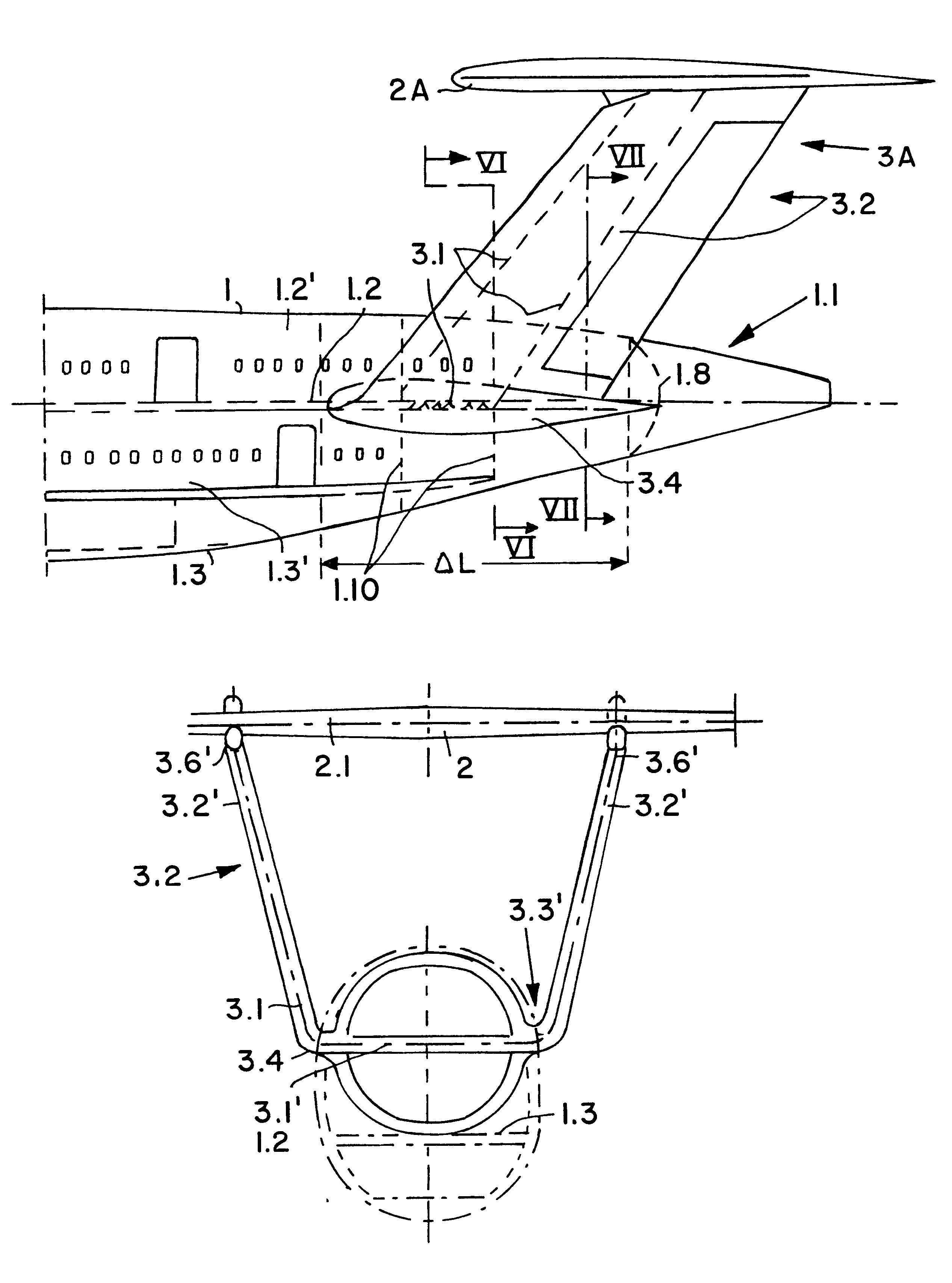
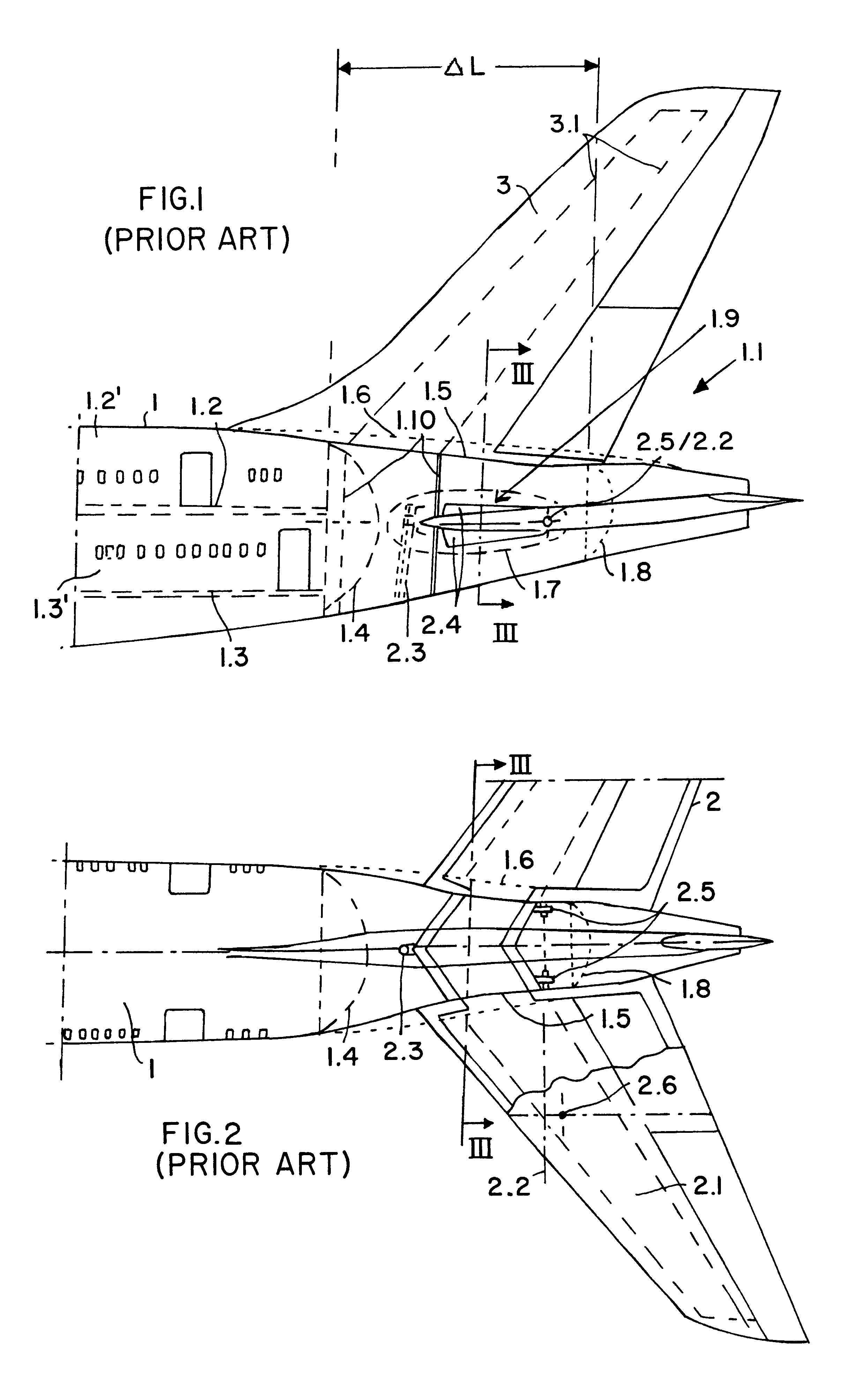
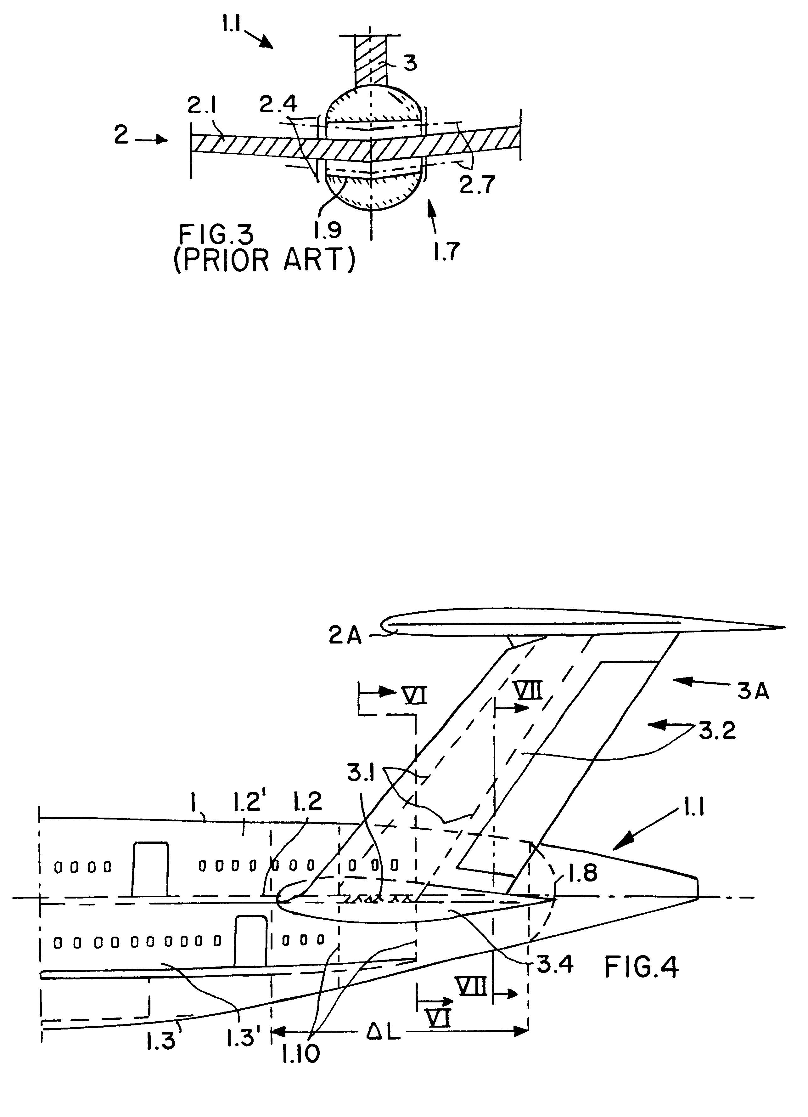
FIGS. 1, 2 and 3 show a portion of a fuselage 1 of a conventional, large capacity commercial aircraft having two passenger decks. The fuselage 1 has an upper deck 1.2 and a main deck 1.3 and a conical-shaped tail section 1.1. A fin and rudder assembly 3 and a tailplane and elevator assembly 2 are attached to the tail section 1.1. A tailplane torsion box 2.1 of the tailplane assembly 2 extends crosswise through the tail section 1.1, preventing this space in the tail section 1.1 from being used as passenger cabin space. In this conventional type of construction, the forces from the fin and rudder assembly 3 are transmitted by a fin torsion box 3.1 to rudder connecting ribs 1.10. These ribs further limit the space that is available for use as passenger cabin space. As a result, a large portion of the space in the tail section 1.1 cannot be used productively as passenger cabin space for the upper deck 1.2 or the main deck 1.3. A pressure bulkhead 1.4 forms the rear closure of the cabins...


PUM


Abstract

An aircraft, preferably a large capacity passenger aircraft with two passenger decks, has a double-T tail assembly arranged on its tail section. The double-T tail assembly includes a double fin and rudder assembly and a tailplane and elevator assembly, and provides a significant increase in the usable passenger cabin space in the tail section of the aircraft. The double fin and rudder assembly has a U-shaped structure and comprises two upright stabilizer fins connected to each other by a horizontal torsion box that fixedly extends crosswise through the fuselage tail section within the floor of a cabin deck. The tailplane and elevator assembly is pivotably mounted on the upper tips of the two upright stabilizer fins in a double-T arrangement.

Description

The invention relates to an aircraft with dual vertical fins and rudders, and particularly a double-T tail assembly. The aircraft is preferably a large capacity commercial passenger aircraft having two passenger decks.BACKGROUND INFORMATIONAircraft with a double fin and rudder assembly, generally called simply a "rudder assembly" herein, arranged on the fuselage are known, particularly as fighter aircraft. In such an application, the double rudder assembly offers advantages over a more common rudder assembly with only a single stabilizer fin, with regard to aerodynamics and weight. For example, the double rudder assembly reduces roll coupling when the rudder is deflected and provides better or more effective rudder action under flow separation conditions (for example, in a tailspin). A double rudder assembly also has a reduced structural weight, for example by reducing bending moments on the rudders, since the span width of each of the vertical fins in a double rudder assembly is sm...

Claims


Application Information

Patent Timeline
Patent Type & Authority Patents(United States)
IPC IPC(8): B64C5/02B64C5/06B64C5/00
CPCB64C5/06B64C5/02
Inventor SPRENGER, WILFRIED
Owner DAIMLER CHRYSLER AEROSPACE AIRBUS
Why Eureka
Try Eureka