Method and apparatus for making thermally bonded electrical cable

a technology of thermal bonding and electrical cables, applied in the direction of insulating conductors/cables, cables, insulated conductors, etc., can solve the problems of limited processing speed, adversely affecting critical electrical properties such as attenuation, crosstalk and transmission, and limited control of bonding characteristics, so as to achieve faster processing speed, increase concentricity, and achieve desired electrical properties

Inactive Publication Date: 2001-08-14
BELDEN TECHNOLOGY INC
View PDF12 Cites 40 Cited by
  • Summary
  • Abstract
  • Description
  • Claims
  • Application Information

AI Technical Summary

Benefits of technology

The present invention produces a cable of two insulated conductors joined along an axially extending groove and having desirable electrical properties with faster processing speeds, increased concentricity, increased control of bonding characteristics, increased color coding capabilities and increased material choices over the prior art. The present invention is directed to a method and apparatus for producing a pair of individually insulated wires joined by thermal bo...

Problems solved by technology

During installation and handling of the cables, the cables are bent, twisted and stretched, and this changes the geometry of the conductors with respect to each other and it adversely affects critical electrical properties such as attenuation, crosstalk and transmission.
This approach offers limited processing speeds which are caused by an additional chemical or solvent application step, and a limited control of bonding characteristics because it is limited to the bond characteristics of the applied chemical or solvent.
There also are limited material choices.
Many thermoplastics have a...

Method used


Image

  • Method and apparatus for making thermally bonded electrical cable
  • Method and apparatus for making thermally bonded electrical cable
  • Method and apparatus for making thermally bonded electrical cable

Examples


Embodiment Construction

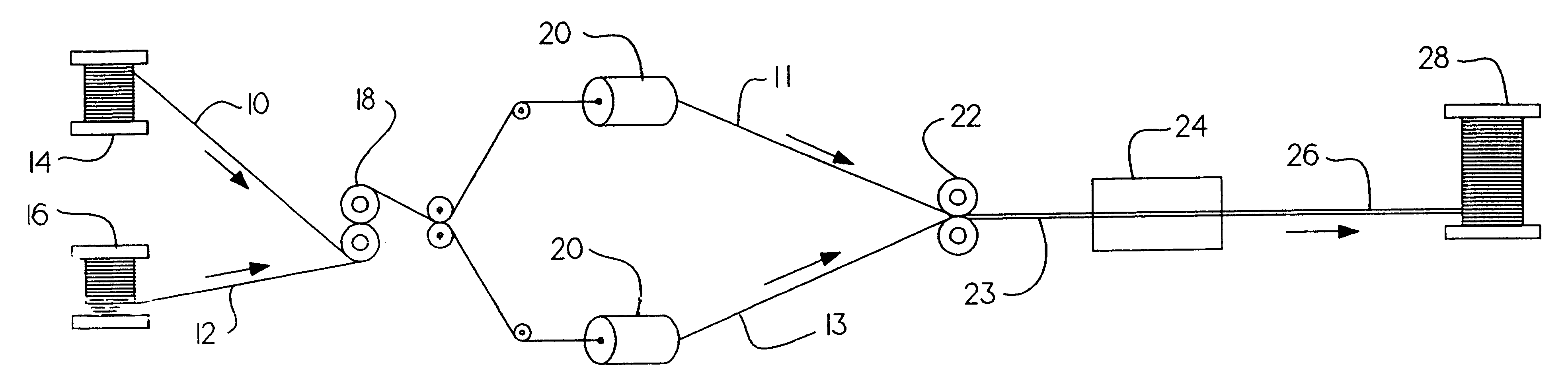
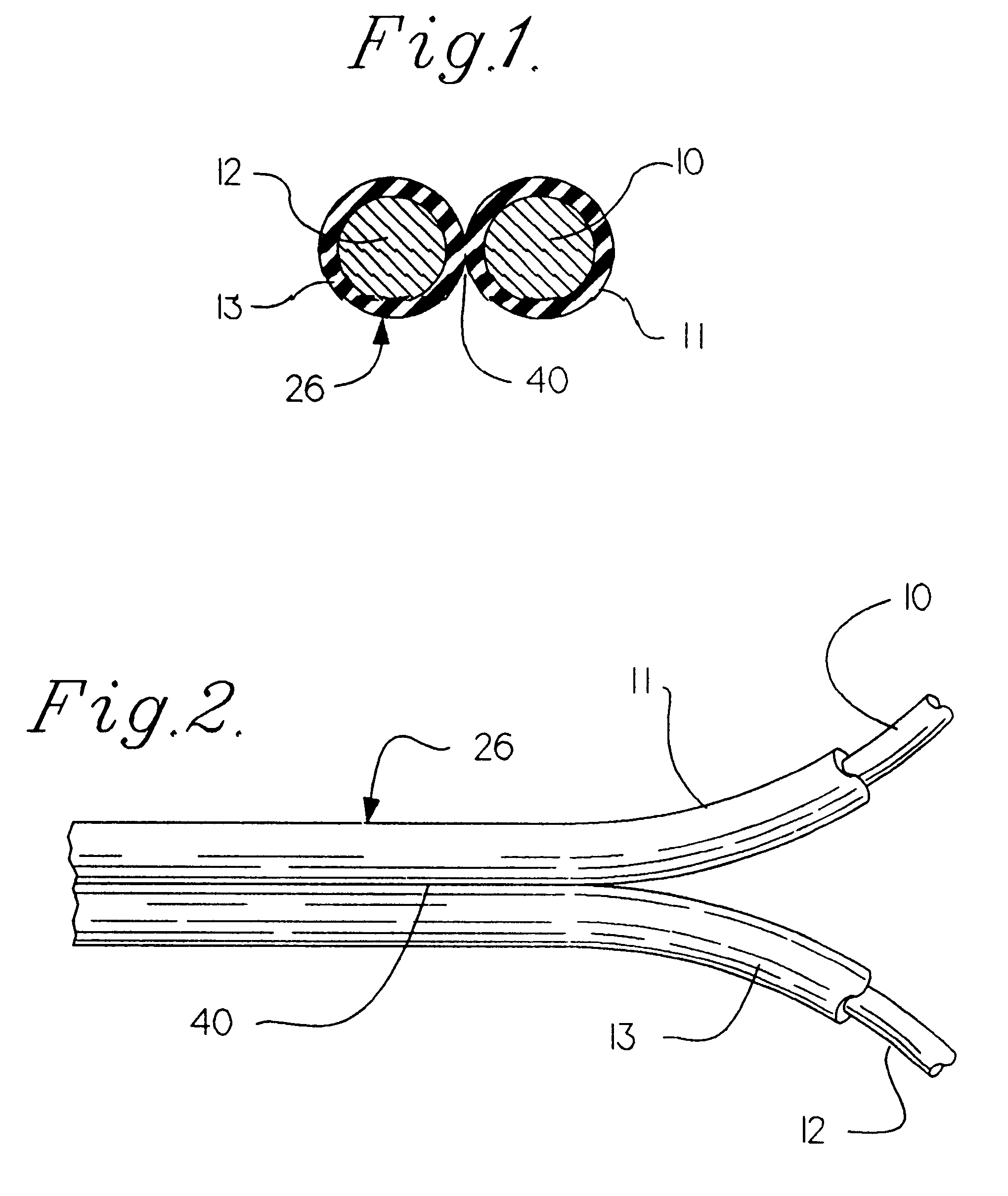
The cable of the present invention comprises separate metallic conductors spaced equal distance from each other and joined to one another with each conductor being concentrically surrounded by a thermoplastic insulating material. FIGS. 1 and 2 illustrate preferred embodiments of the cable produced by the present method and apparatus. The cable, 26, includes two conductors, 10, 12, each individually and concentrically coated with a thermoplastic insulating material, 11, 13, joined along an axially extending groove, 40.

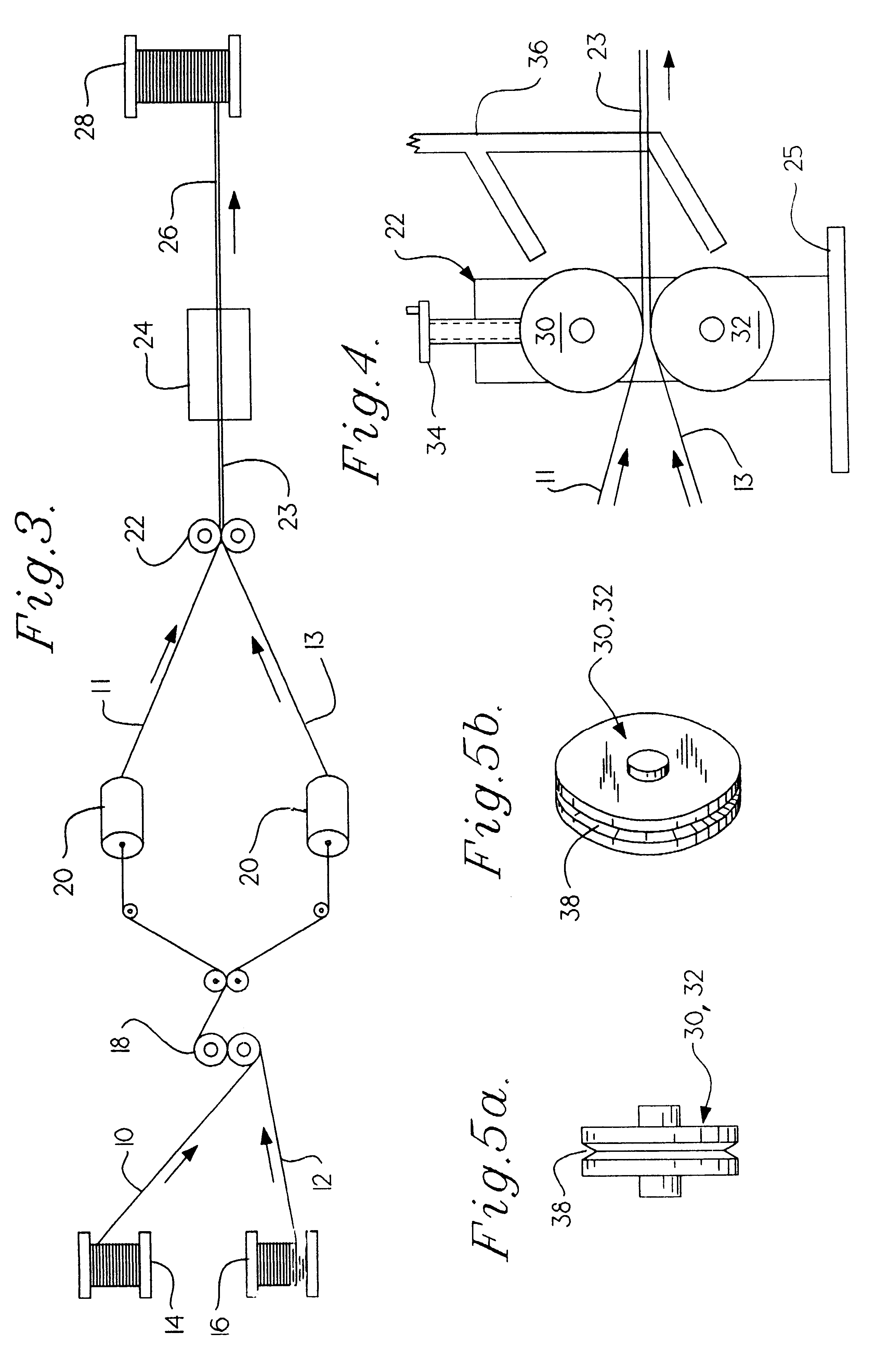
FIG. 3 illustrates the production system embodying the present invention, wherein two lengths of bare conductor 10, 12 are continuously withdrawn from supply spools 14, 16 and moved through the system by means not shown. The conductors first pass through a tension equalizing device 18, where the tension of each is equalized with that of the other and maintained throughout the system. Next, the conductors are concentrically coated with a heated thermoplastic insulating m...


PUM


Abstract

A method for making cable of at least two thermoplastic insulated electrical conductors by thermal bonding. Two electrical conductors are moved into an extruder and are coated independently with heated thermoplastic insulation which maintains concentricity of each conductor with respect to the surrounding insulation. The insulated conductors are held in a spaced relationship until the insulation sets and then the heated insulated conductors are touched together causing the heated insulation to fuse together thereby joining them.

Description

This invention relates to a method and apparatus for bonding two separate independent insulated electrical wires together. This is done in a manner that maintains the concentricity of each electrical conductor with respect to the insulation. The invention uses heated thermoplastic material that surrounds each electric conductor. When the insulation has set, the insulated conductors are touched together and are bonded to each other by the heated thermoplastic insulation.BACKGROUND OF THE INVENTION AND PROBLEM PRESENTED TO INVENTORModern twisted pair cable consists of two separate insulated wires paired through twisting means. Ideally, the insulation of each conductor is applied in such a manner that the concentricity of the conductor with respect to the insulation is maintained. When the conductors are paired, the electrical properties of the cable are maintained at a desirable level.During installation and handling of the cables, the cables are bent, twisted and stretched, and this ...

Claims


Application Information

Patent Timeline
IPC IPC(8): H01B13/00
CPCH01B13/0023
Inventor HARDEN, SCOTT W.HARDEN, DAVID R.
Owner BELDEN TECHNOLOGY INC
Why Eureka
Try Eureka