Push rod activated grease nozzle

a technology of grease nozzle and push rod, which is applied in the direction of manual lubrication, machines/engines, lighting and heating apparatus, etc., can solve the problems of wheel wear over time, tread wear, and tread wear, so as to achieve the effect of reliably dispense a metered amount of lubrican

Inactive Publication Date: 2001-08-21
WESTINGHOUSE AIR BRAKE TECH CORP
View PDF21 Cites 16 Cited by
  • Summary
  • Abstract
  • Description
  • Claims
  • Application Information

AI Technical Summary

Benefits of technology

It is, therefore, a primary object of the present invention to provide a nozzle assembly that will reliably dispense a metered amount of lubricant onto the flange of the wheel of a railroad locomotive.

Problems solved by technology

Due to their contact with the railway track, the wheels of a locomotive suffer wear over time, particularly on their treads and to a lesser extent on their flanges.
The treads, of course wear as a result of their direct contact against the top of the rail.
During braking the treads may suffer wear more severely if the wheels should happen to slip or lockup as they slide along the rail.
The wheel flanges suffer wear due to their contact with the inside surfaces of the rails.
In these systems nozzles have, through the years, proven to be the least reliable component of the wheel flange lubrication system.
These prior art nozzles have not fared well in the railroad environment where they are intended to be used.
Dirt, dust and other debris can work their way into the nozzle and after a while impede the movement of the internal ball valve.

Method used


Image

  • Push rod activated grease nozzle
  • Push rod activated grease nozzle

Examples


Embodiment Construction

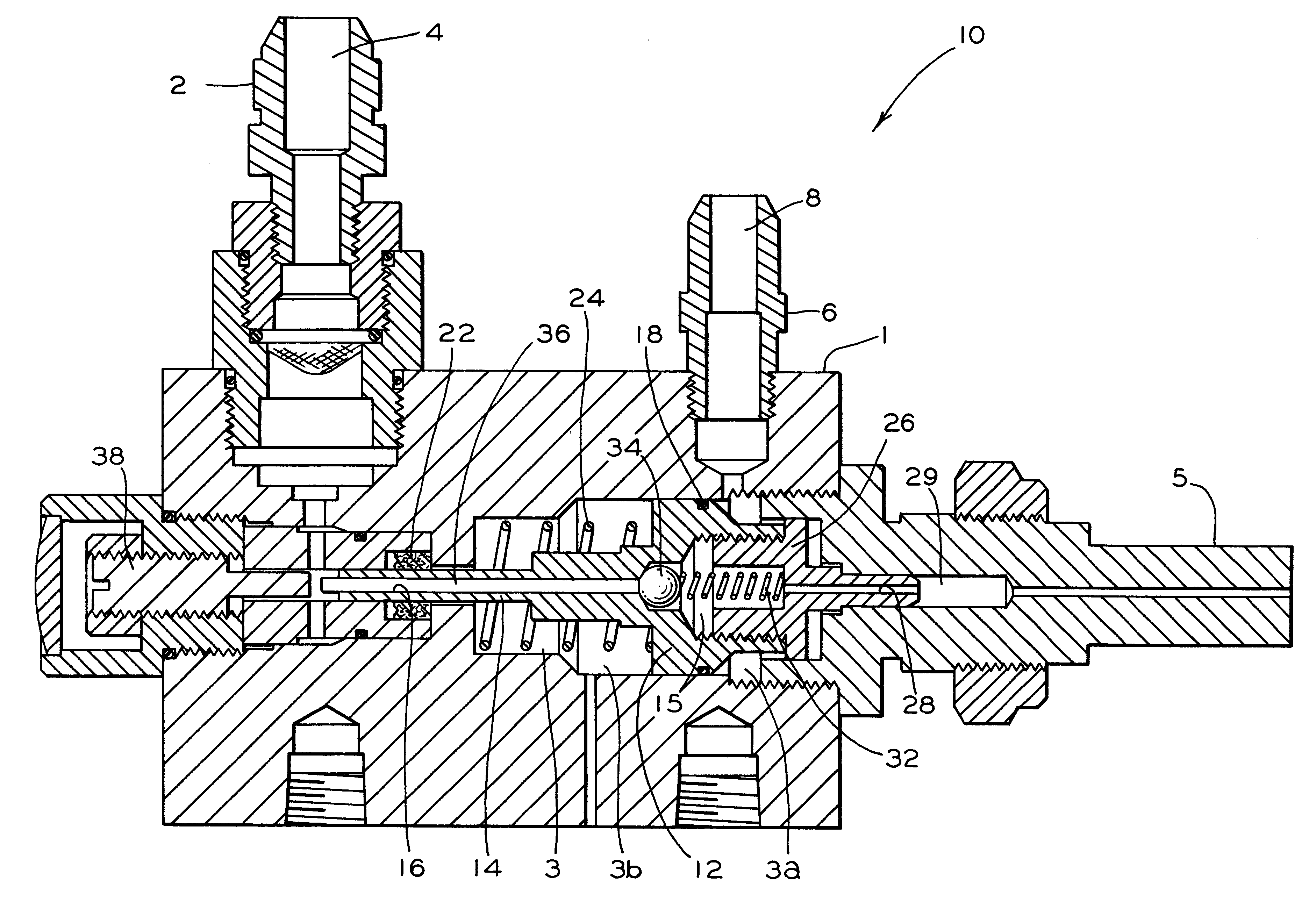
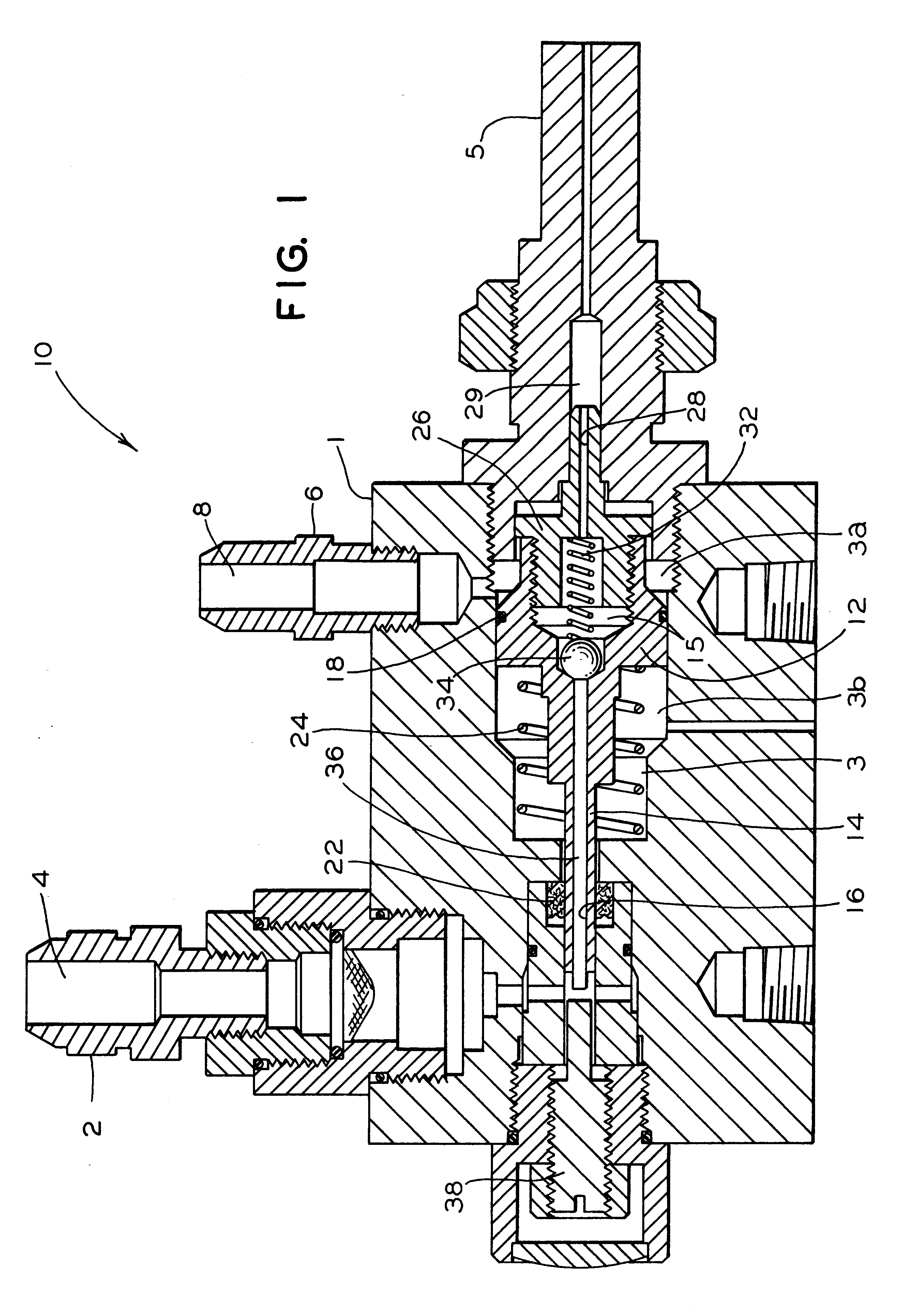
Reference is now made to FIG. 1. Illustrated therein is an assembly, generally referred to as 10, according to a first embodiment of the invention. Assembly 10 is used to dispense a lubricant. The lubricant used in the assembly 10 may be a variety of lubricants; however, it is presently preferred that such lubricant is a grease. For convenience the lubricant may be referred to as a grease hereinafter and the words may be interchangeable.

Such assembly 10 comprises a housing member 1 which includes a cavity 3 and a nozzle member 5 connected to the housing 1. The housing member 1 further includes a grease fitting 2 which is connectable to a source of grease under pressure (not shown). Grease fitting 2 has a grease passage 4 which carries grease to the inner part of the housing member 1. There is also an fluid pressure fitting 6 which is connectable to a source of fluid pressure (not shown). Such fluid pressure fitting 6 has a fluid pressure inlet passage 8 which is in fluid communicati...


PUM


Abstract

The present invention provides an assembly for dispensing a lubricant. The assembly comprises a housing with a cavity and a nozzle member connected to the housing. The housing further includes a lubricant passage connectable to a source of pressurized lubricant and a fluid pressure inlet passage connected to a source of fluid pressure. The assembly further includes a piston member having a predetermined configuration with a first side in fluid communication with the fluid pressure passage and a second side and having a piston cavity formed within. There is a first bore extending through the piston. A retainer member is connected to such first side of the piston member. A valve device is biased by an urging device against the first bore preventing grease from exiting. Another urging device biases the piston to such closed position. A push rod is disposed within the first bore and extends a predetermined distance beyond an end of the second side of the piston. When fluid pressure enters the cavity, it forces the piston to the left and the urging device forces the ball valve and the push rod to the left until the push rod contacts resistance. The piston member continues to move to the left for such predetermined distance until it also contacts resistance. The push rod thereby preventing the valve device from pressing against the piston bore and thus permits grease to flow. Grease passes through a second bore, is mixed with fluid pressure and is expelled as a spray from the nozzle member.

Description

The present invention relates, in general, to a lubrication system used to lubricate the flanges of the wheels of a railroad locomotive and, more particularly, the present invention relates to a flange lubricator nozzle assembly.Wheel treads are designed to adhere to the running surface (top) of the rails of a railway track essentially by means of friction. It is this friction between the treads and the top of the rails that allows the wheels to gain traction on the rails as the wheels rotate and thereby propel the train along the tracks. A wheel flange is that tapered projection that extends completely around the inner portion of the rim of a wheel. The wheel flanges are designed to keep the wheels or wheelsets on the railway track by limiting lateral movement of the wheels or wheelsets against the inside surface of either rail.Due to their contact with the railway track, the wheels of a locomotive suffer wear over time, particularly on their treads and to a lesser extent on their ...

Claims


Application Information

Patent Timeline
Patent Type & Authority Patents(United States)
IPC IPC(8): F16N3/12F16N5/00F16N5/02F16N3/00
CPCF16N5/02F16N3/12
Inventor CARROLL, JOHN B.
Owner WESTINGHOUSE AIR BRAKE TECH CORP
Why Eureka
Try Eureka