Expandable sequencing tray

a sequencing tray and expandable technology, applied in the field of expandable sequencing tray, can solve the problems of increasing the spacing between gel wells, reducing the spacing, and consuming a lot of labor

Inactive Publication Date: 2001-08-21
SORENSON BIOSCI
View PDF2 Cites 25 Cited by
  • Summary
  • Abstract
  • Description
  • Claims
  • Application Information

AI Technical Summary

Benefits of technology

This invention provides structures that address the incompatibility between conventional 96 sample well array format and the gel well comb pattern format currently being introduced into vertical electrophoresis techniques. While particular emphasis is given to this specific format incompatibility issue, the invention has application to the harmonization of incompatible formats in other applications, both within and unrelated to electrophoresis technologies. The invention provides, in tray format, an array of sample wells organized for loading by a multiple tip pipettor device in conventional fashion. The tray is structured to permit increasing (or reducing) the spacing between adjacent wells, along at least one coordinate axis, to permit sample extraction by a multiple tip pipettor having a different tip spacing than that of the sample-loading pipettor. In an exemplary embodiment, the sample wells are arranged in rows (ranks) and files. The sample wells associated with individual rows are connected in substantially fixed position by means of relatively rigid structural members. These row members are interconnected by mechanisms which allow for adjustment of the spacing between rows. Ideally, the mechanisms connecting respective rows are structured and arranged to provide coordinated movement over the limited range required; that is, the spacings between adjacent rows should remain approximately identical across the array. A preferred form of such mechanisms comprises tethering members (such as flexible hinges or strands) The invention further contemplates a novel multi tip pipettor in which the spacings between adjacent tips is 10.8 mm. It also contemplates a novel rack with individual well sockets spaced and arrange to accept and hold an expanded tray of the invention..

Problems solved by technology

The loading of DNA samples onto the automated fluorescence DNA sequencer has not yet been automated, and thus remains a very labor intensive portion of the overall process.
The loading step has constituted the most tedious part of the sequencing process.
Unfortunately, as the press for greater through put has gained momentum, the spacings between gel wells has been further decreased, and standardization based upon the 96 well format has been abandoned with respect to the electrophoresis operation.
Reliance upon the conventional 9 mm head is thus inappropriate.
This step is relatively labor intensive and time consuming.
It also introduces an additional opportunity for error in the overall procedure.
It is economically unfeasible to retrofit all of the extant laboratory facilities currently wedded to the 96 well sample format to adopt a 10.8 sample well spacing.

Method used


Image

  • Expandable sequencing tray
  • Expandable sequencing tray
  • Expandable sequencing tray

Examples


Embodiment Construction

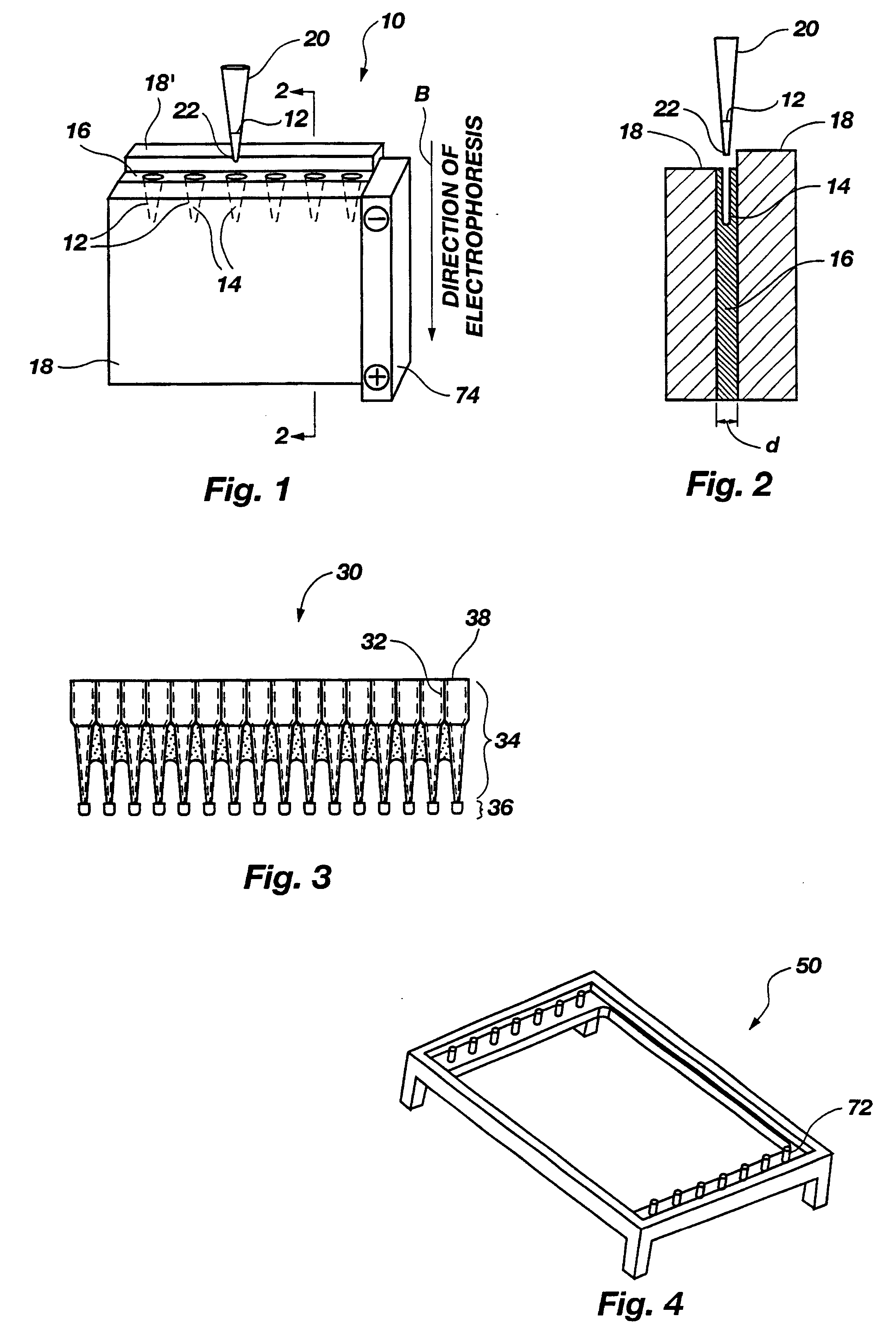
FIGS. 1 and 2 illustrate an electrophoresis device, generally 10, receiving biological sample material 12 in individual gel wells 14 formed within a thin film 16 of sequencing gel held sandwiched between spaced structural plates 18. A potential is applied across the gel by means of a fixture 19. Charge-carrying molecules forming the sample 12 migrate downwardly in the direction of arrow B, and are separated under the influence of the applied voltage in accordance with their respective molecular weights. The samples 12 are dispensed into individual wells 14 by individual micro pipette tips 20, which are conventionally carried by the head of a pipettor (not shown). The plates 18 are separated by a distance d (FIG. 2), which is typically quite small; e.g., 0.20 mm.

FIG. 3 illustrates one embodiment of a pipette tip device, generally 30. A plurality of interconnected tips 32 are disposed in substantially parallel orientation and in side-by-side alignment. The tips 32 are hollow, and each...


PUM

PropertyMeasurementUnit
center-to-center distanceaaaaaaaaaa
distanceaaaaaaaaaa

Abstract

A DNA sequencing tray (92) holds an array of sample wells (82) in a rank and file pattern by means of rigid file members (85) connected by flexible mechanisms (87) permitting the pattern to be expanded to change the center-to-center spacing between adjacent wells (82) form 9 mm to 10.8 mm.

Description

This invention pertains generally to adjustment of the intersection coordinates of an array characterized by regularly spaced target locations between steps of a procedure applied to the array. It is particularly directed to electrophoresis applications, and provides means for adjusting the spacings between target sites within a conventional sample well array to the spacing pattern of electrophoresis gel wells. The invention has particular application to DNA sequencing procedures.Electrophoresis is used for a large number of applications. For example, DNA sequencing can be undertaken to determine the genetic composition, and specifically the nucleotide sequence, of a sample of DNA.Many existing electrophoresis applications are undertaken using so-called "running tanks." In that procedure, a sample-containing gel is disposed in an electrophoresis chamber in the tank. Electric current is then applied to the gel by means of an electrode in the tank to cause electrophoresis of the sampl...

Claims


Application Information

Patent Timeline
Patent Type & Authority Patents(United States)
IPC IPC(8): B01L3/00G01N35/10
CPCB01L3/5085B01L3/50855G01N35/1067Y10S435/809G01N2035/1069
Inventor BROPHY, JOHN M.PRICE, WEST L.MACKERT, STEPHEN C.
Owner SORENSON BIOSCI
Why Eureka
Try Eureka