Method and apparatus for operation control of melting furnace

a technology of operation control and melting furnace, which is applied in the direction of lighting and heating equipment, furnaces, combustion types, etc., can solve the problems of narrow visual field, inability to accurately perform visual observation, and inability to observe accurately, so as to reduce the amount of heat consumed, minimize damage to the melting furnace, and facilitate the molten slag

Inactive Publication Date: 2001-08-28
EBARA CORP
View PDF16 Cites 22 Cited by
  • Summary
  • Abstract
  • Description
  • Claims
  • Application Information

AI Technical Summary

Benefits of technology

An object of the present invention is to solve the above-described problems associated with melting furnaces and to detect the melt condition of molten slag in a melting furnace and control the amount of heat supplied to the melting furnace so that the temperature of the molten slag is within a predetermined range, thereby reducing the amount of heat consumed, obtaining favorable molten slag and minimizing damage to the melting furnace. Another object of the present invention is to automatically process an image of the inside of a melting furnace, thereby eliminating variations in the operation control of the melting furnace due to individual differences among operators. Still another object of the present invention is to enable the melt condition of molten slag in a melting furnace to be remotely monitored through a television camera at a position remote from the melting furnace, thereby improving the working environment of the furnace running operation.

Problems solved by technology

However, the thermocouple detects the temperature of the gas in the furnace because it cannot directly measure the temperature of molten slag, which is at high temperature.
However, visual observation made from the access hole of the melting furnace through quartz glass involves problems.
For example, because the size and shape of the access hole are limited, the visual field is narrow, and smoke in the furnace can adhere to the quartz glass.
Therefore, the visual observation cannot accurately be performed.

Method used


Image

  • Method and apparatus for operation control of melting furnace
  • Method and apparatus for operation control of melting furnace
  • Method and apparatus for operation control of melting furnace

Examples


Embodiment Construction

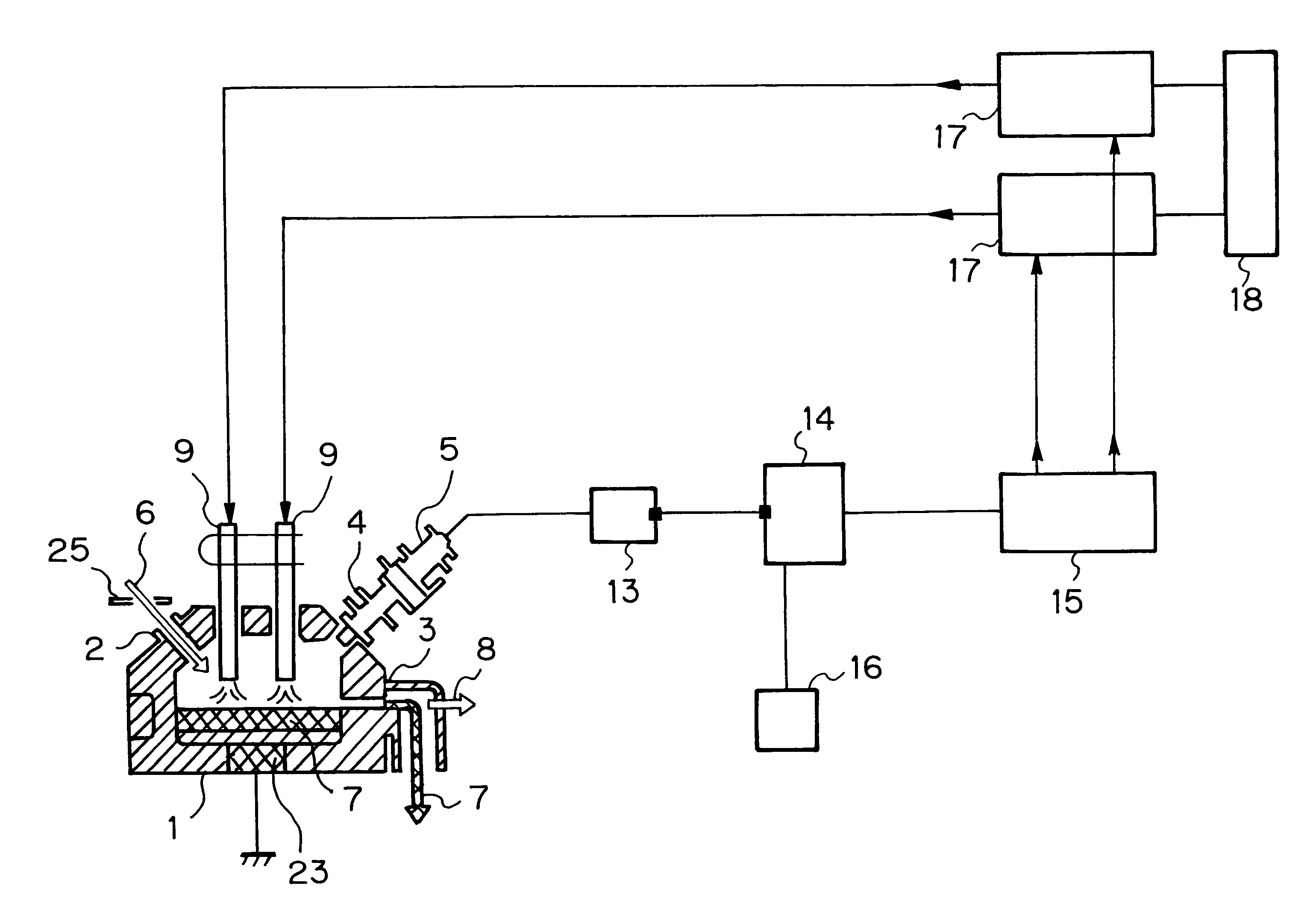
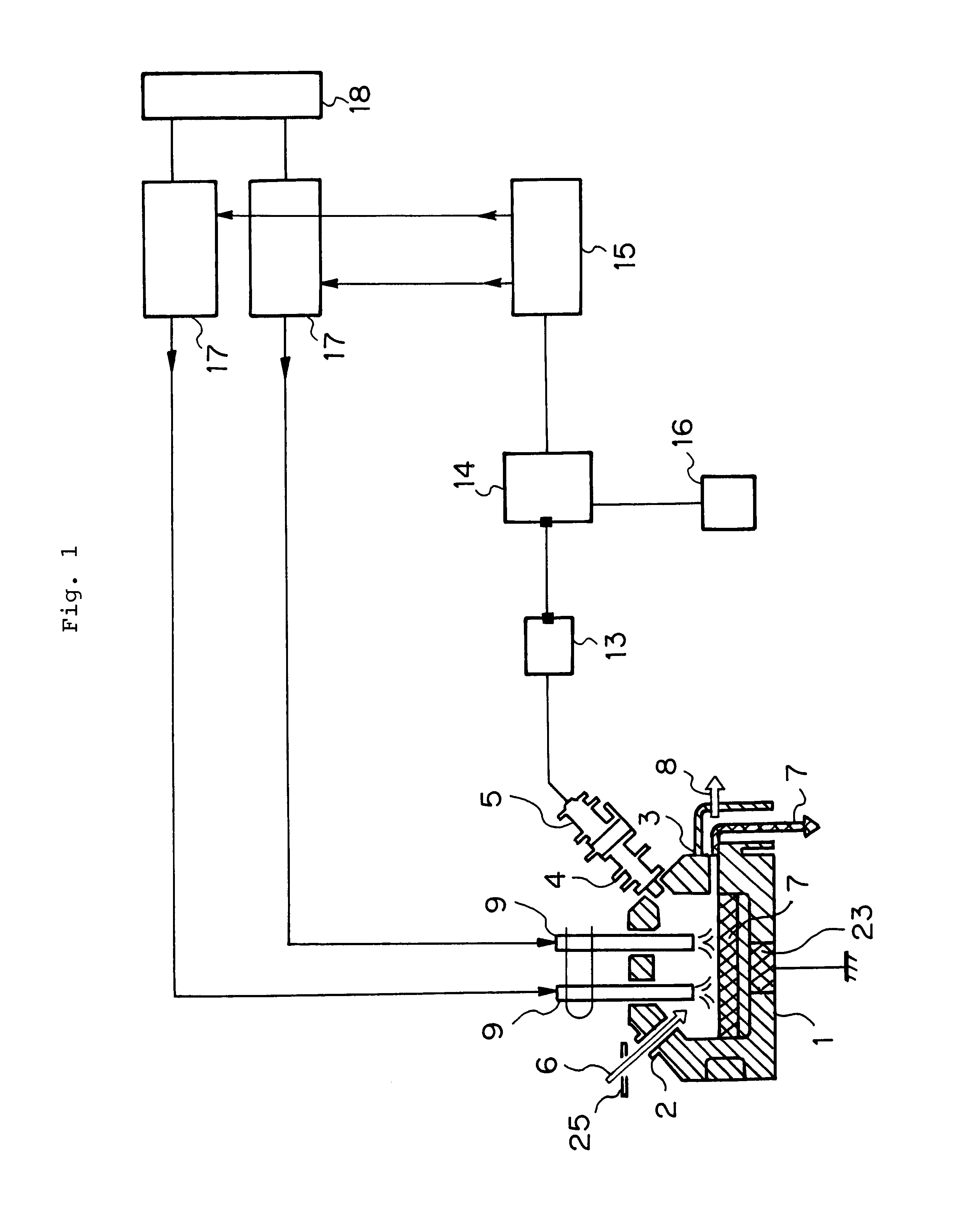
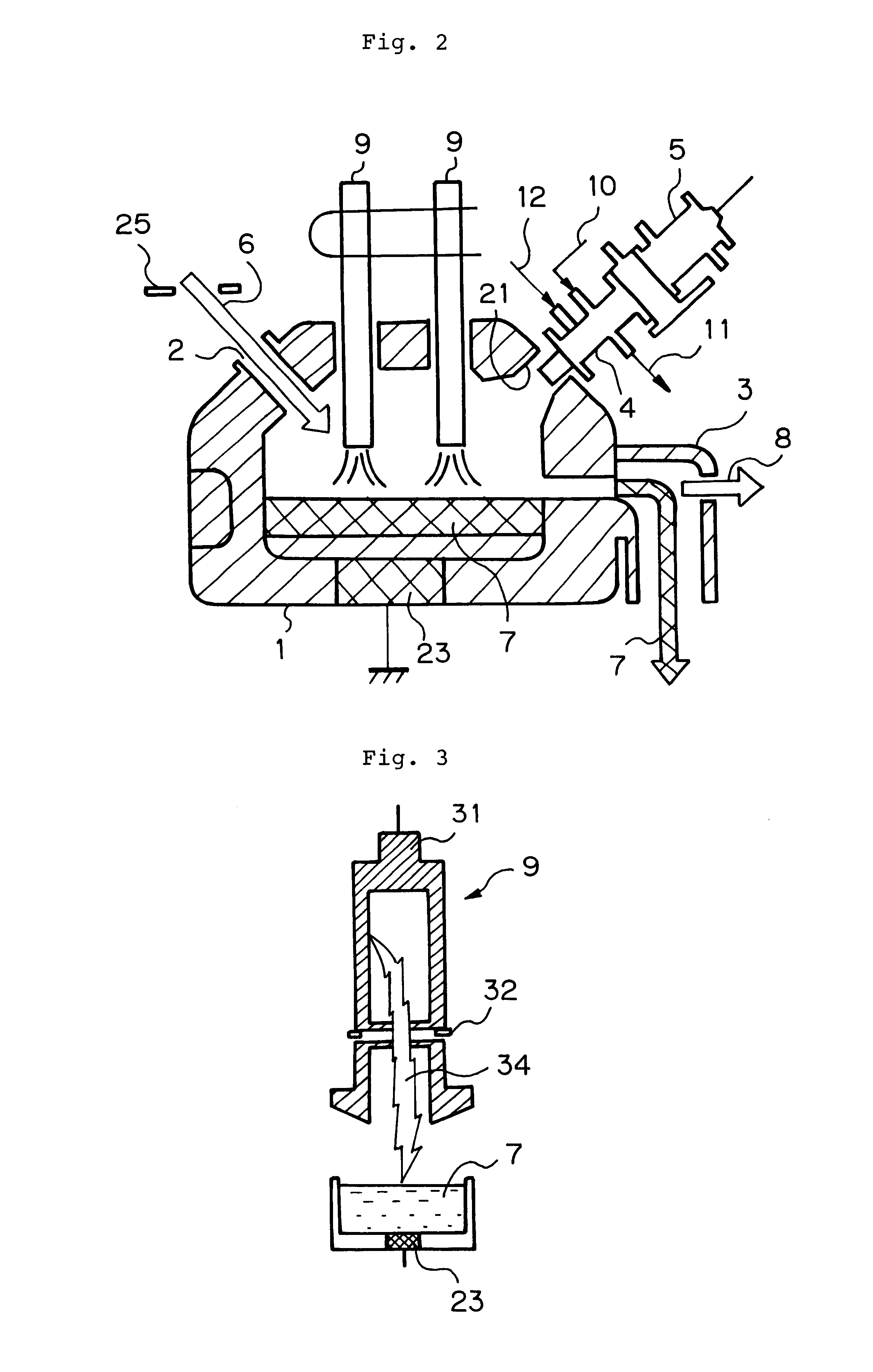
An embodiment of the present invention will be described with reference to the drawings. The arrangement of the operation control apparatus according to the present invention is schematically shown in FIG. 1. FIG. 2 is an enlarged sectional view of a melting furnace in FIG. 1. In FIGS. 1 and 2, the melting furnace 1 has a supply opening 2 for incineration ash, a discharge opening 3 for molten slag, an access hole 21, torches 9, and so forth. Incineration ash 6 containing incineration fly ash, which is supplied from the supply opening 2, floats over molten slag 7 in the melting furnace. While being caused to flow toward the discharge opening 3, the incineration ash 6 is heated with the torches 9 and thus successively melted into molten slag 7. As the amount thereof increases, the molten slag flows out and drops through the discharge opening 3 and is then sent to a slag-cooling device (not shown). Gas 8 generated in the melting furnace is discharged from the neighborhood of the discha...


PUM

PropertyMeasurementUnit
temperatureaaaaaaaaaa
sizeaaaaaaaaaa

Abstract

An operation control method and apparatus are provided for a melting furnace 1 having a supply opening 2 for incineration ash 6, a discharge opening 3 for molten slag 7, and a heat source 9 for applying an amount of heat to the supplied incineration ash. The method includes the steps of imaging the vicinity of the surface of molten slag 7 heated by an amount of heat transferred from the heat source with a television camera 5 to obtain an electronic image, differentiating a high-temperature region in the electronic image that is not lower than a predetermined temperature (1,300° C.) from a low-temperature region in the electronic image that is lower than the predetermined temperature, and controlling the amount of heat applied to the incineration ash from the heat source so that the size of the differentiated high-temperature region reaches a predetermined value. The television camera 5 has a relay lens 4 and is placed so that the surface portion of the molten slag 7, to which an amount of heat is transferred from the heat source 9, lies approximately in the center of the image.

Description

The present invention relates to an operation control method and apparatus for a melting furnace having a supply opening for incineration ash, a discharge opening for molten slag, and a heat source for applying an amount of heat to the supplied incineration ash.To reduce the volume of incineration ash resulting from incineration of municipal refuse or the like and to make heavy metals contained in the ash insoluble or harmless, melt treatment of incineration ash, that is, a treatment in which incineration ash is melted at high temperature in a melting furnace and discharged from the melting furnace as molten slag, is carried out. In such a melting furnace, it is necessary, on the one hand, to raise the temperature in the melting furnace to a relatively high temperature, e.g. in the vicinity of 1,300.degree. C., in order to melt incineration ash, and on the other, it is important to control the temperature so as not to exceed 1,300.degree. C. with a view to minimizing damage to the f...

Claims


Application Information

Patent Timeline
Patent Type & Authority Patents(United States)
IPC IPC(8): C03B5/00C03B5/24C03B5/02F27B3/10F27B3/28
CPCC03B5/005F27B3/28C03B5/24C03B5/025Y02P40/50F23J1/00
Inventor JIMBO, HAJIMEKIKUCHI, TAKESHIAMEMIYA, TOSHIROUGOHDA, YASUYUKI
Owner EBARA CORP
Why Eureka
Try Eureka