
Retractable trolling motor

a technology of a trolling motor and a rotor, which is applied in the direction of marine propulsion, propulsive elements, vessel construction, etc., can solve the problems of noise level, exhaust emissions, relative complexity, size and weight, and limiting the access to the water in the area of the motor mount,

Inactive Publication Date: 2001-08-28
BRP US
View PDF2 Cites 25 Cited by
  • Summary
  • Abstract
  • Description
  • Claims
  • Application Information

AI Technical Summary

Benefits of technology

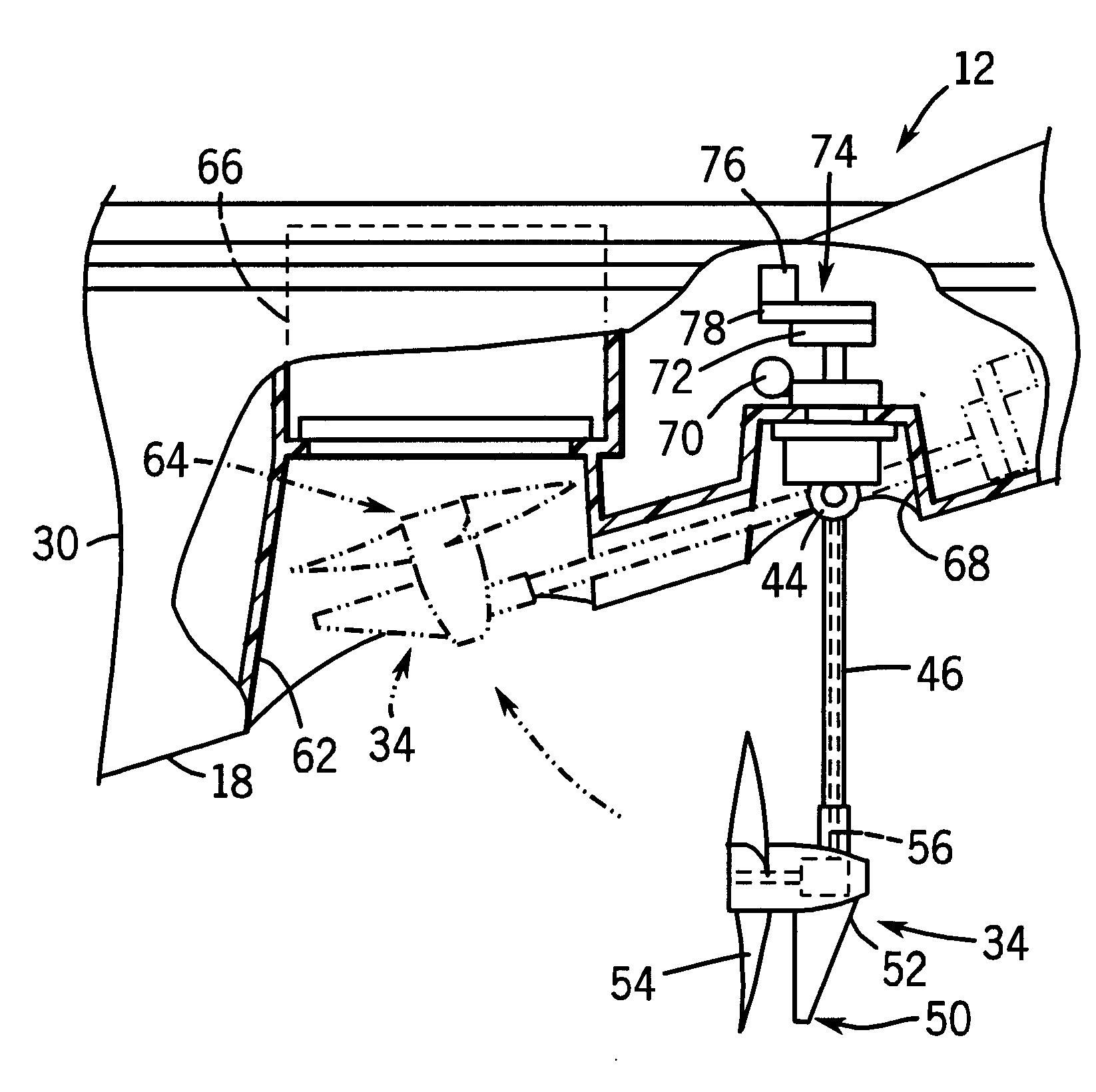
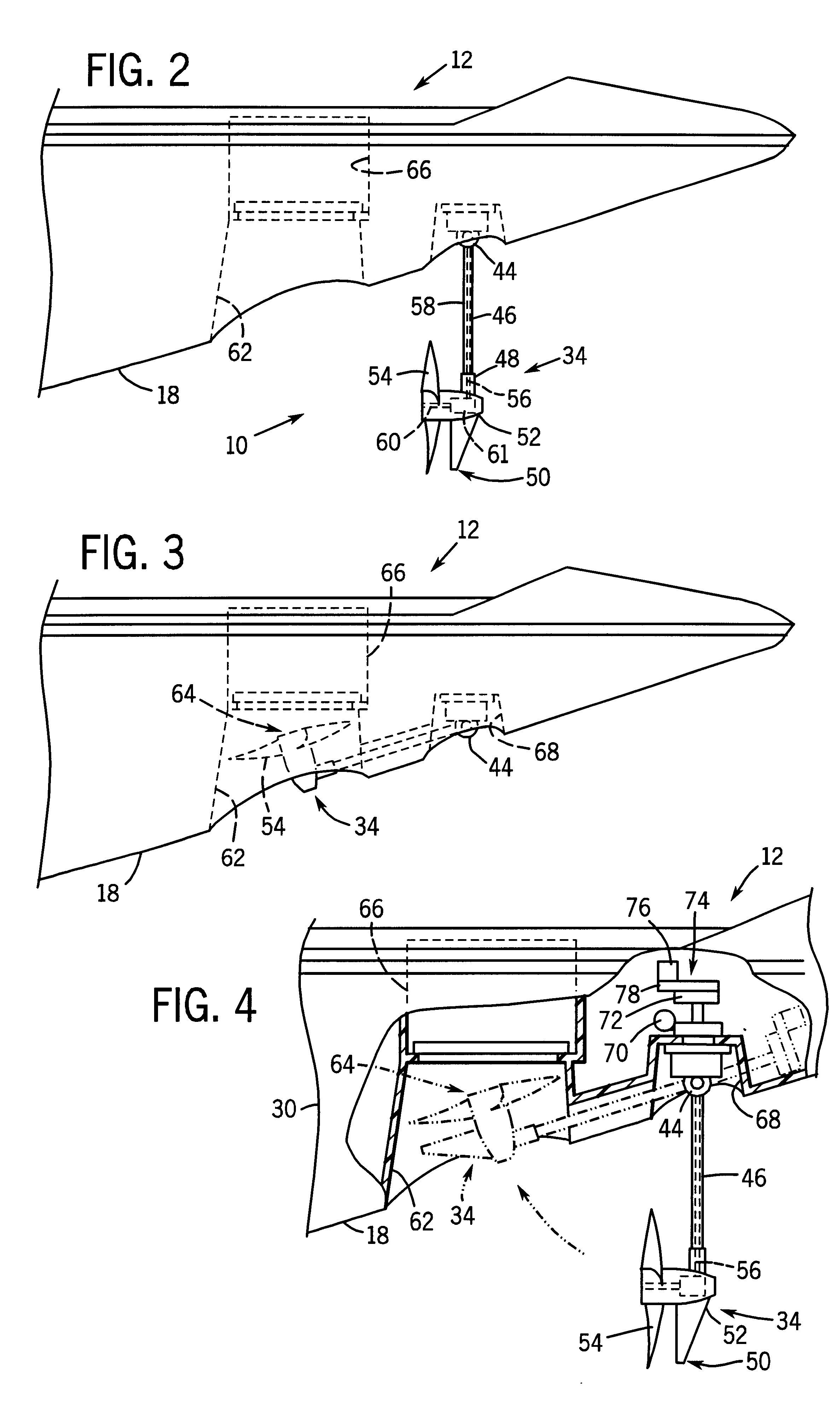
The propulsion assembly is stowed at a stowed position, in which a portion of the assembly fits within a recessional housing in the hull of the watercraft. The recessional housing may be an integral part of the watercraft, or it may be retrofitted to a particular watercraft. The recessional housing stows the propulsion assembly while non-operational, and may provide access to the assembly for maintenance and cleaning, and may reduce drag.

Problems solved by technology

Drawbacks of such drives, however, include their noise levels, exhaust emissions, relative complexity, size and weight.
The resulting structure is somewhat cumbersome and occupies useful space on the deck, limiting access to the water in the area of the motor mount.
Moreover, while much energy and creativity have been invested in boat designs, the aesthetics and aerodynamics of the hull may be somewhat impaired by the trolling motor and mount positioned on the deck, typically adjacent to the bow.
Furthermore, conventional trolling motors only provide thrust at a point adjacent to the perimeter of a watercraft, thereby allowing external forces such as wind to force the watercraft out of alignment with the desired direction of movement across the water.

Method used


Image

  • Retractable trolling motor
  • Retractable trolling motor
  • Retractable trolling motor

Examples


Embodiment Construction

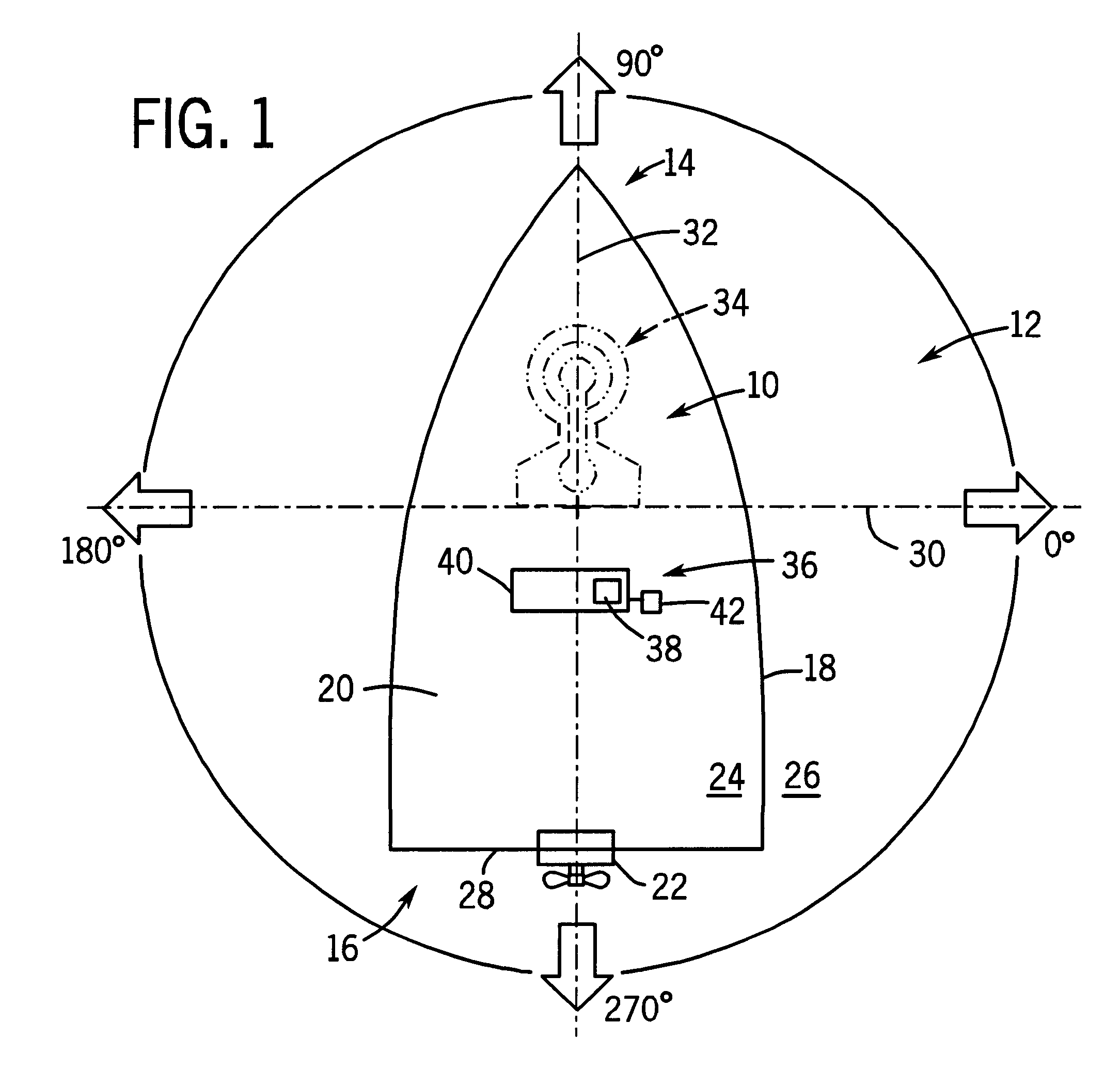
Turning now to the drawings, FIG. 1 illustrates a top view of a propulsion system 10 adapted for and disposed in a watercraft 12. The watercraft 12 has a bow 14, a stem 16, a hull 18, and a cabin 20. The watercraft 12 may also have a rear propulsion unit or motor 22, mounted either inboard 24 or outboard 26 at a transom 28. For orientation purposes, FIG. 1 illustrates the watercraft 12 as having a transverse centerline 30 and a longitudinal centerline 32. The propulsion system 10 preferably includes a propulsion assembly 34 mounted to the hull 18 forward the transverse centerline 30. The propulsion system 10 may also have a control system 36, which may include instruments 38 disposed on a console 40 and a foot pedal 42 for hands-free control of the propulsion assembly 34. These components of the system may be similar to those currently available for control of conventional trolling motors and electric outboards.

FIG. 2 illustrates a side view of an embodiment of the propulsion assemb...


PUM


Abstract

A propulsion system for a watercraft is provided, which may be an integral part of a watercraft or may be retrofitted to a particular watercraft. The propulsion system is mounted to the hull in a central area, such as forward of a transverse centerline of the hull. The propulsion system includes a propulsion assembly coupled to a retractable arm, which is pivotable between a stowed and operational position. In the stowed position at least a portion of the propulsion assembly may be received within a recessional housing formed in the hull.

Description

1. Field of the InventionThe present invention relates generally to electric propulsion units for recreational watercraft. More specifically, the present invention relates to propulsion units which mount in a forward area of the watercraft.2. Description of the Related ArtRecreational watercraft are typically used for a variety of activities such as fishing, cruising, water skiing, and so forth. To move the watercraft across the water, an adequate amount of thrust is necessary depending on the particular activity. The thrust may be provided by a variety of propulsion systems, typically electrically or mechanically powered. Mechanical propulsion systems generally include outboard or inboard / outboard engine-driven propeller systems. In the field of propulsion systems for watercraft, and particularly for pleasure craft, various electrical and mechanical propulsion devices have been proposed and adopted for use. In general, such systems include internal combustion engines drives and ele...

Claims


Application Information

Patent Timeline
Patent Type & Authority Patents(United States)
IPC IPC(8): B63H20/10B63H20/00
CPCB63H20/10B63H20/007
Inventor GRIFFITH, SR., THOMAS E.JONES, DAVID D.TYLER, CALVIN
Owner BRP US
Learn More