
Patient-worn energy delivery apparatus

a technology of energy delivery apparatus and patient, which is applied in the direction of electrotherapy, heart defibrillator, therapy, etc., can solve the problems of heart muscle quivering, halting normal contractions, and affecting the normal flow of blood,

Inactive Publication Date: 2001-08-28
ZOLL MEDICAL CORPORATION
View PDF3 Cites 326 Cited by
  • Summary
  • Abstract
  • Description
  • Claims
  • Application Information

AI Technical Summary

Benefits of technology

The apparatus further provides means for measuring the electrical energy as it is being delivered to the body of the patient through a plurality of electrodes interposed between the defibrillator and the patient. The apparatus periodically measures the voltage and current of the pulse being delivered. In a preferred embodiment, these measurements are rapidly periodically taken, on the order of every 94 microseconds, and stored for later analysis. The pulse is terminated when the desired energy level has been delivered to the patient. In the event of a malfunction, such as an overvoltage condition sensed by the apparatus, the pulse can be truncated so as to prevent harm to the patient or damage to the apparatus.
The defibrillator may further include a plurality of silicon controller rectifiers and opto-triacs and selected ones of the capacitors may be serially connected with other capacitors and respective ones of the silicon controlled rectifiers may be serially interposed between adjacent capacitors. Each of the silicon controlled rectifiers may be controllable with the opto-triacs which cause the silicon controlled rectifiers to conduct responsive to a therapy initiation command from the controller. This arrangement of components minimizes the size and weight of the apparatus, aiding patient comfort while still being able to generate these high energy levels without damaging the internal components.

Problems solved by technology

Each may lead to death within minutes unless corrected by the appropriate electrical stimulation.
One of the most deadly forms of heart arrhythmias is ventricular fibrillation, which occurs when the normal, regular electrical impulses are replaced by irregular and rapid impulses, causing the heart muscle to stop normal contractions and to begin to quiver.
Normal blood flow ceases, and organ damage or death may result in minutes if normal heart contractions are not restored.
Because the victim has no noticeable warning of the impending fibrillation, death often occurs before the necessary medical assistance can arrive.
Because time delays in applying the corrective electrical treatment may result in death, implantable pacemakers and defibrillators have significantly improved the ability to treat these otherwise life threatening conditions.
Pacemakers and defibrillators that apply corrective electrical pulses externally to the patient's chest wall also are used to correct such lifethreatening arrhythmias but suffer from a drawback insofar as it may not be possible to apply the device in time during an acute arrhythmic emergency to save the patient's life.
Long term hospitalization, however, is frequently impractical due to its high cost, or due to the need for patients to engage in normal daily activities.
There also are many patients susceptible to heart arrhythmias who are at temporary risk of sudden death.
For example, patients who have suffered a myocardial infarction are at substantial risk of tachyarrhythmias for several weeks thereafter.
Additionally, patients awaiting implantation of an automatic defibrillator may require an external defibrillator to be close at hand, in case they experience a life-threatening tachyarrhythmia.
Furthermore, some patients who may benefit from an implantable defibrillator may face an inordinate risk from the surgery required for implanting such a device.

Method used


Image

  • Patient-worn energy delivery apparatus
  • Patient-worn energy delivery apparatus
  • Patient-worn energy delivery apparatus

Examples


Embodiment Construction

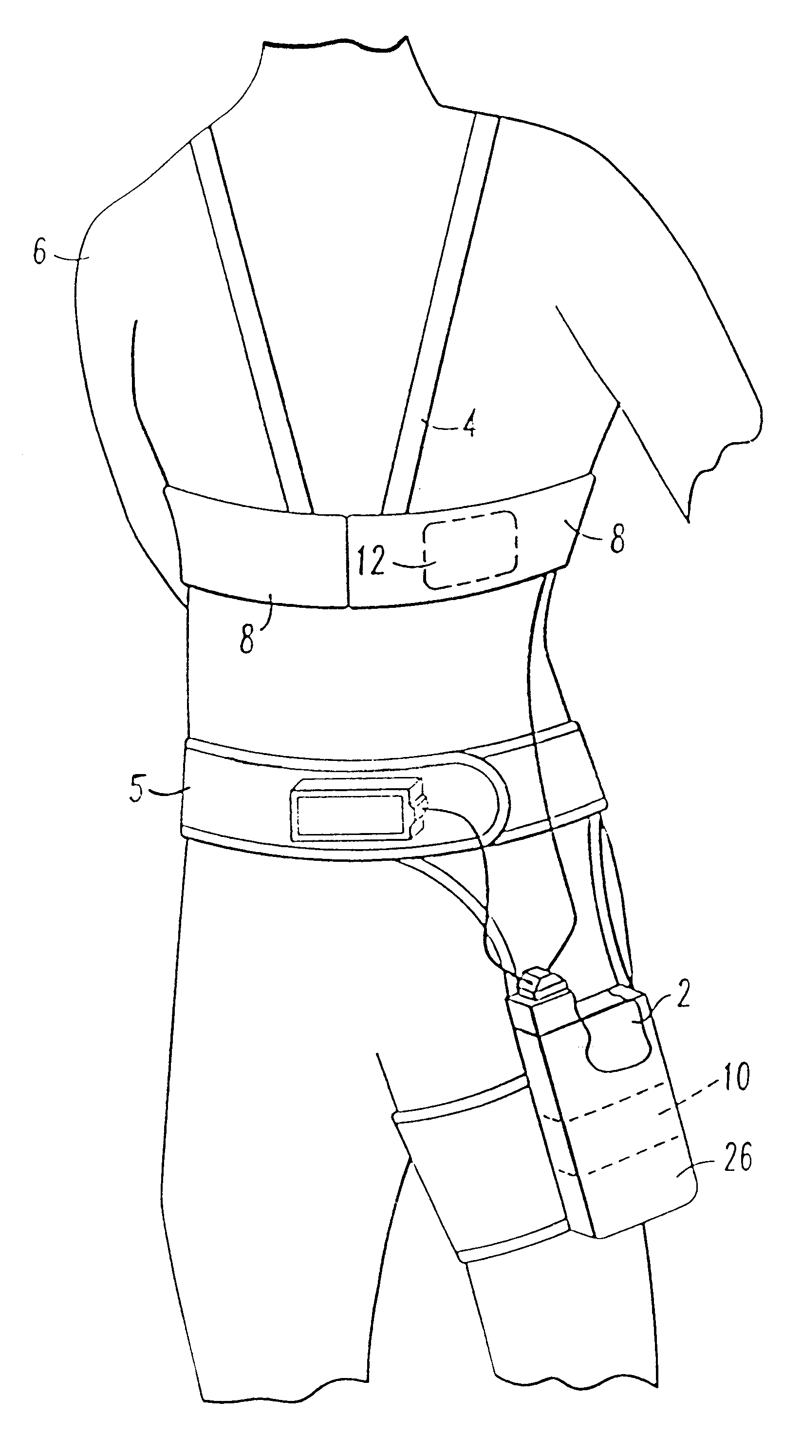
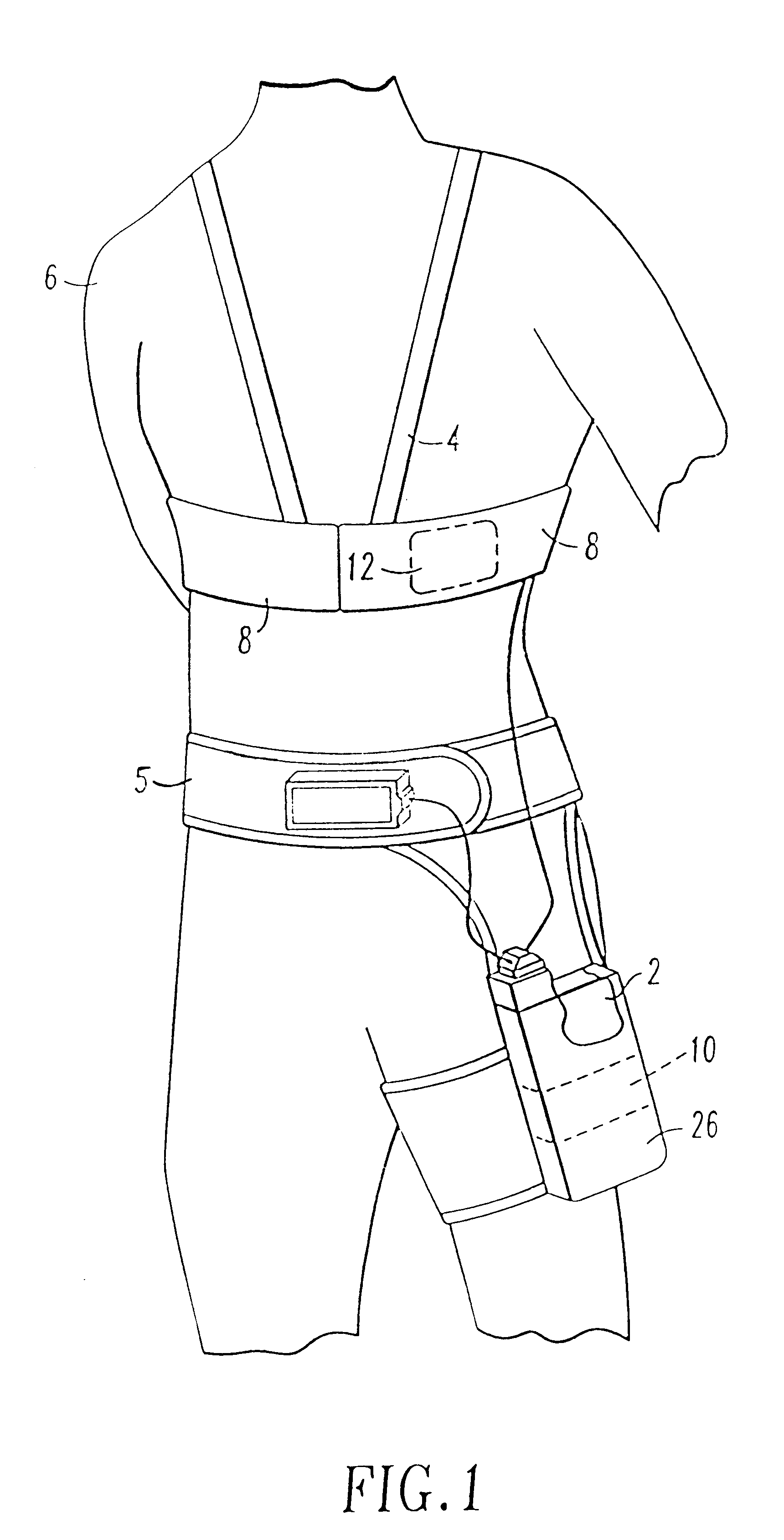
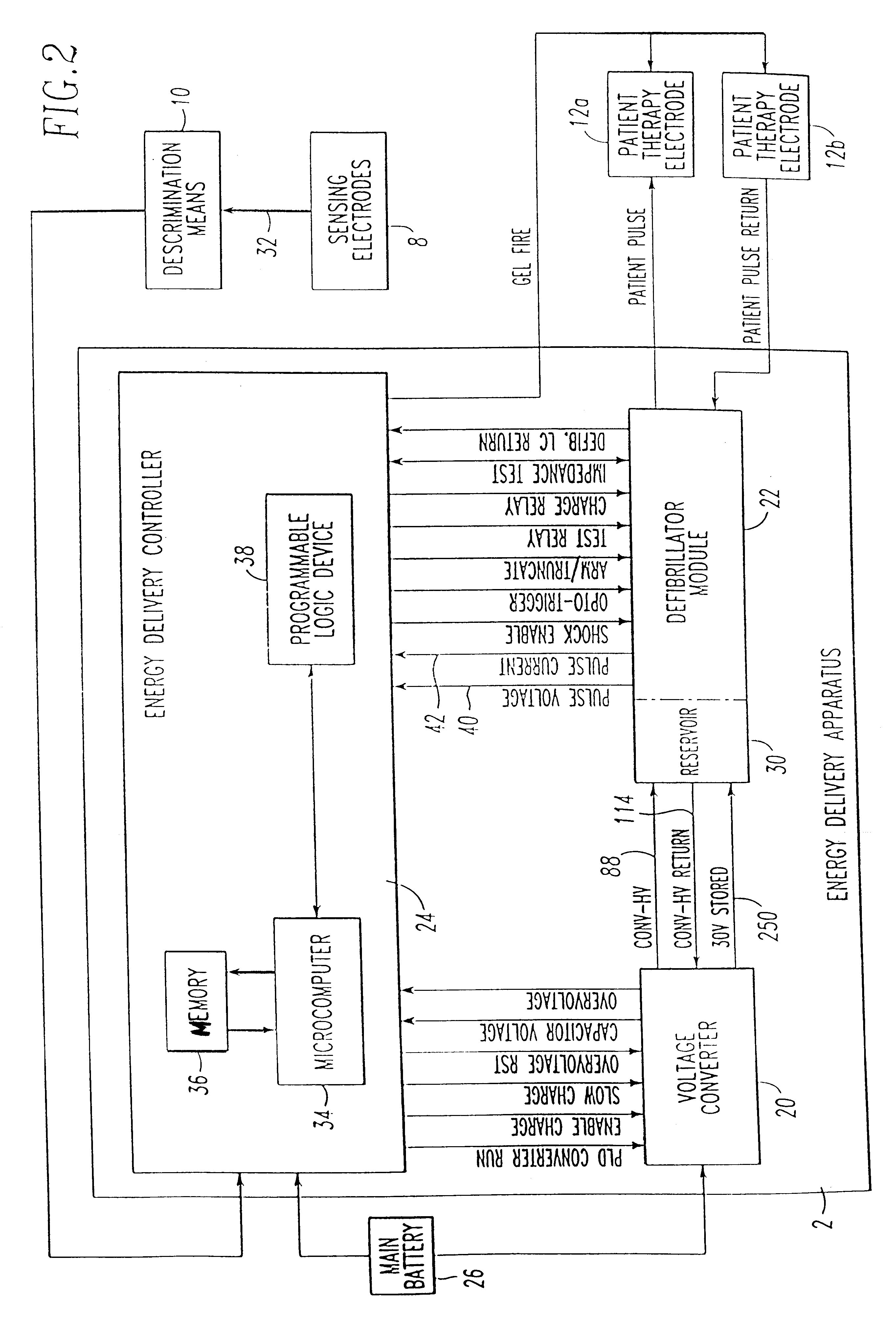
The invention herein provides a patient-worn energy delivery apparatus for imparting electrical energy to the body of the patient in response to the occurrence of a treatable cardiac condition. In FIG. 1, energy delivery apparatus 2 is shown being used in conjunction with carrier means 4 in the form of an upper body harness or garment and a waist-worn holster 5 to be worn by patient 6. Apparatus 2 also can include monitoring means 8, internal to the chest garment, for continuously sensing the patient's heart condition. Signals 32, indicative of the patient's heart condition can be provided by monitoring means 8 to discrimination means 10 for determining the presence of a treatable cardiac condition. When such a condition exists, apparatus 2 can deliver electrical therapy in the form of preprogrammed electrical pulses to patient 6 using, for example, pulse electrodes 12a,12b, preferably located anterior at the apex of the heart and posterior between the shoulders. The pulse electrode...


PUM


Abstract

A patient-worn energy delivery apparatus for imparting electrical therapy to the body of a patient responsive to an occurrence of a treatable condition includes a voltage converter for converting electrical energy from an initial voltage to a final voltage, and a defibrillator electrically coupled between the converter and the patient and having an energy reservoir for receiving the electrical energy. The defibrillator produces preshaped electrical pulses such as defibrillation pulses and cardioversion pulses. The apparatus additionally includes an energy delivery controller electrically coupled to the patient and the converter and the defibrillator. The controller causes the converter to provide the electrical energy to the defibrillator at a specific charging rate in response to an energy level in the reservoir. The apparatus may include a plurality of electrodes interposed between the defibrillator and the patient and each electrode preferably has an impedance reducing means contained therein. One embodiment of the apparatus may include a H-bridge to produce a positive-going pulse segment and the negative-going pulse segment within the biphasic exponential signals. The apparatus periodically measures the energy as it is being delivered to the patient and can pre-emptively stop or truncate the pulse in the event an error condition is detected, such as an overvoltage condition or if the energy level approaches a predetermined level. The electrical components which store and release the energy minimize the size and expense of the apparatus, while isolating the microcomputer from the high energy levels as the therapeutic pulse is delivered.

Description

1. Field of the InventionThis invention relates generally to the treatment of heart defects by the administration of electrical therapy. More particularly, this invention relates to an energy-delivery apparatus for imparting the electrical therapy to the heart.2. Description of the Related ArtTechnology is available for correcting excessively slow heart rates (bradycardia) using implantable devices, commonly referred to as pacemakers, which deliver microjoule electrical pulses to a slowly beating heart in order to speed the heart rate up to an acceptable level. Also, it is well known to deliver high energy shocks (e.g., 180 to 360 joules) via external paddles applied to the chest wall in order to correct excessively fast heart rates, and prevent the possible fatal outcome of ventricular fibrillation or certain ventricular tachycardias. Bradycardia, ventricular fibrillation, and ventricular tachycardia are all electrical malfunctions (arrhythmias) of the heart. Each may lead to death...

Claims


Application Information

Patent Timeline
Patent Type & Authority Patents(United States)
IPC IPC(8): A61N1/39
CPCA61N1/39A61N1/3937A61N1/3912A61N1/3904
Inventor GLEGYAK, JOHN A.PEDUZZI, DAVID J.RUSSIAL, JOSEPHKAIB, THOMAS E.
Owner ZOLL MEDICAL CORPORATION
Learn More