Method of forming a printed circuit board

Inactive Publication Date: 2001-08-28
WILBUR ROBERT L
View PDF20 Cites 7 Cited by
  • Summary
  • Abstract
  • Description
  • Claims
  • Application Information

AI Technical Summary

Benefits of technology

The present invention relates to a method of forming a printed circuit board, without the use of expensive di

Problems solved by technology

However, in many experimental situations it may not be e

Method used


Image

  • Method of forming a printed circuit board
  • Method of forming a printed circuit board
  • Method of forming a printed circuit board

Examples


Embodiment Construction

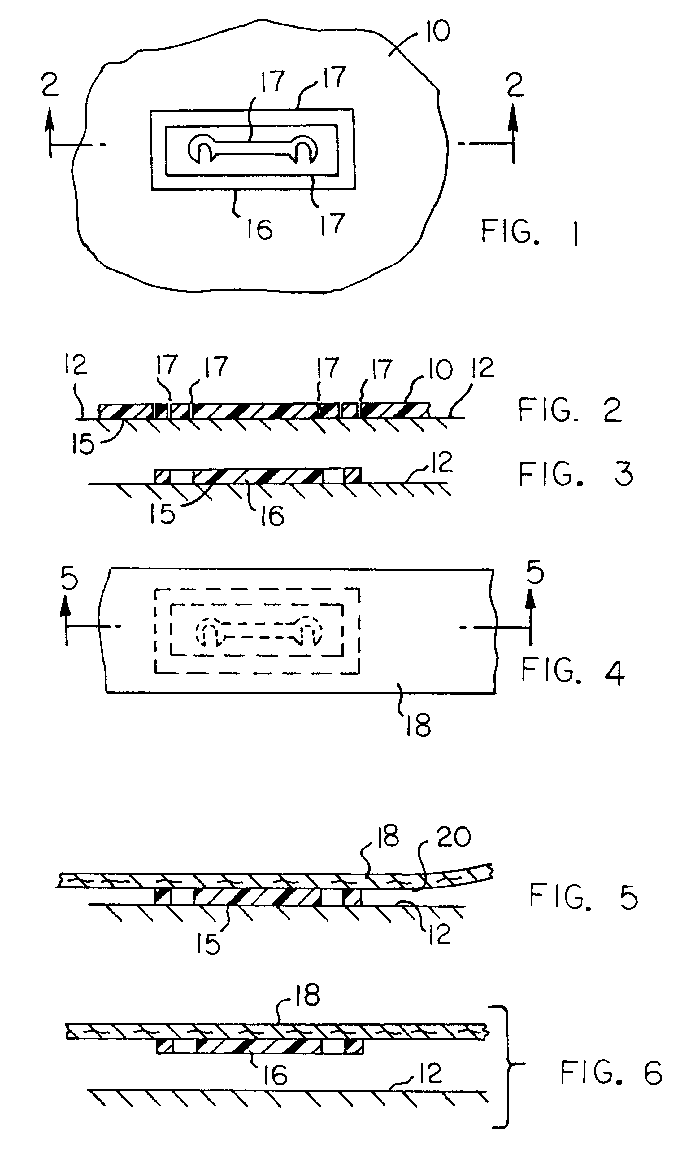
FIG. 1, is a plan view of an illustrative circuit pattern formed on a plastic masking sheet, by cutting, burning, or laser action.

FIG. 2, is a sectional view taken on line 2--2 in FIG. 1.

FIGS. 1 and 2, show a sheet of masking material 10 adhesively secured to a flat substrate surface 12. In FIG. 2, the lower face of sheet 10 is a pre-coated with a first contact adhesive 15, whereby sheet 10 is releasably secured to support surface 12. Support surface 12 is glossy (non-porous), whereby the surface acts as a release surface at a subsequent point in the manufacturing cycle.

FIG. 3, is a sectional view taken in the same direction as FIG. 2, but after excess material has been removed from the masking sheet.

A cutting mechanism is applied to the exposed (upper) surface of sheet 10, to form a pattern 16 in the sheet. The cutting mechanism can be a manually operated knife, or (in a more elaborate system) a plotter cutter, a low power laser controlled by a computer that is connected to a scann...


PUM

PropertyMeasurementUnit
Flexibilityaaaaaaaaaa
Electrical conductoraaaaaaaaaa
Adhesivityaaaaaaaaaa

Abstract

A printed circuit board can be formed by a method that includes the step of cutting a circuit pattern out of a low cost plastic sheet material, and transferring the pattern onto a tape. The tape, with the pattern adhesively attached, is transferred onto a conductive film surface on a dielectric board. Thereafter, the tape is removed, leaving the pattern on the conductive film. An acid-etching step is performed on the exposed areas of the conductive film, after which the pattern is removed from the non-etched areas of the conductive film.

Description

BACKGROUND OF THE PRESENT INVENTIONSummary of the Present InventionThis invention relates to a method of forming a printed circuit board, and especially to a method that can be used to build printed circuit boards without special tooling or equipment. The invention is particularly applicable to the fabrication of prototype circuit boards or circuit boards for relatively low volume production (where tooling expense is a major factor).Circuit boards produced by a mass production process, on a large volume scale, can be fabricated with special tools and dies configured to the particular circuit design that is to be used. However, in many experimental situations it may not be economically feasible to construct special tools and dies. The present invention is concerned with the situation where the circuit designer may want to produce limited numbers of printed circuit boards to meet low volume requirements, or for experimental or prototype purposes.The present invention relates to a meth...

Claims


Application Information

Patent Timeline
IPC IPC(8): C23F1/02H05K3/00H05K3/06
CPCC23F1/02H05K3/0079Y10T156/1062H05K2203/0537Y10T29/49155H05K3/061
Inventor WILBUR, ROBERT L.
Owner WILBUR ROBERT L
Why Eureka
Try Eureka