Electroslag facing process

a technology of electroslag and facing process, which is applied in the field of electroslag cladding, can solve the problems of not realizing the fusion of metals, too complicated and expensive devices, and very expensive solid electrode production

Inactive Publication Date: 2001-09-04
ZAKRYTOE AKTSIONERNOE OBSCHESTVO ELMET ROL GRUPPA MEDOVARA
View PDF13 Cites 8 Cited by
  • Summary
  • Abstract
  • Description
  • Claims
  • Application Information

AI Technical Summary

Problems solved by technology

The most up-to-date method of cladding of the above-mentioned products is a cladding with a liquid metal which can drastically reduce the cost of the process and products and use the cladding materials of almost any chemical compositions, the production of which in the form of solid electrodes is very expensive or impossible in separate cases.
However, the use of a conventional, non-current carrying mould could not realize this process on an industrial scale, as the device for its realization was too complicated and expensive.
This method is implemented in industry, however, it does not realize the fusion of the metal to be clad and billet to be clad, but it brazes them.
This limits the feasibility of combination of different metals: for example, this method can be used for coating steel rolls from low-alloyed steels with a high-speed steel.
However, his method cannot be applied for cast iron rolls.
In addition, the above-mentioned method is performed within very limited ranges of technological parameters, thus often leading to the violation of continuity of the brazed joint of the roll and metal being clad.
The U.S. Pat. No. 4,305,451 of Feb. 15, 1981 describes the method of ...

Method used


Image

  • Electroslag facing process
  • Electroslag facing process
  • Electroslag facing process

Examples


Embodiment Construction

The principle of the of the present invention method is reduced to the following.

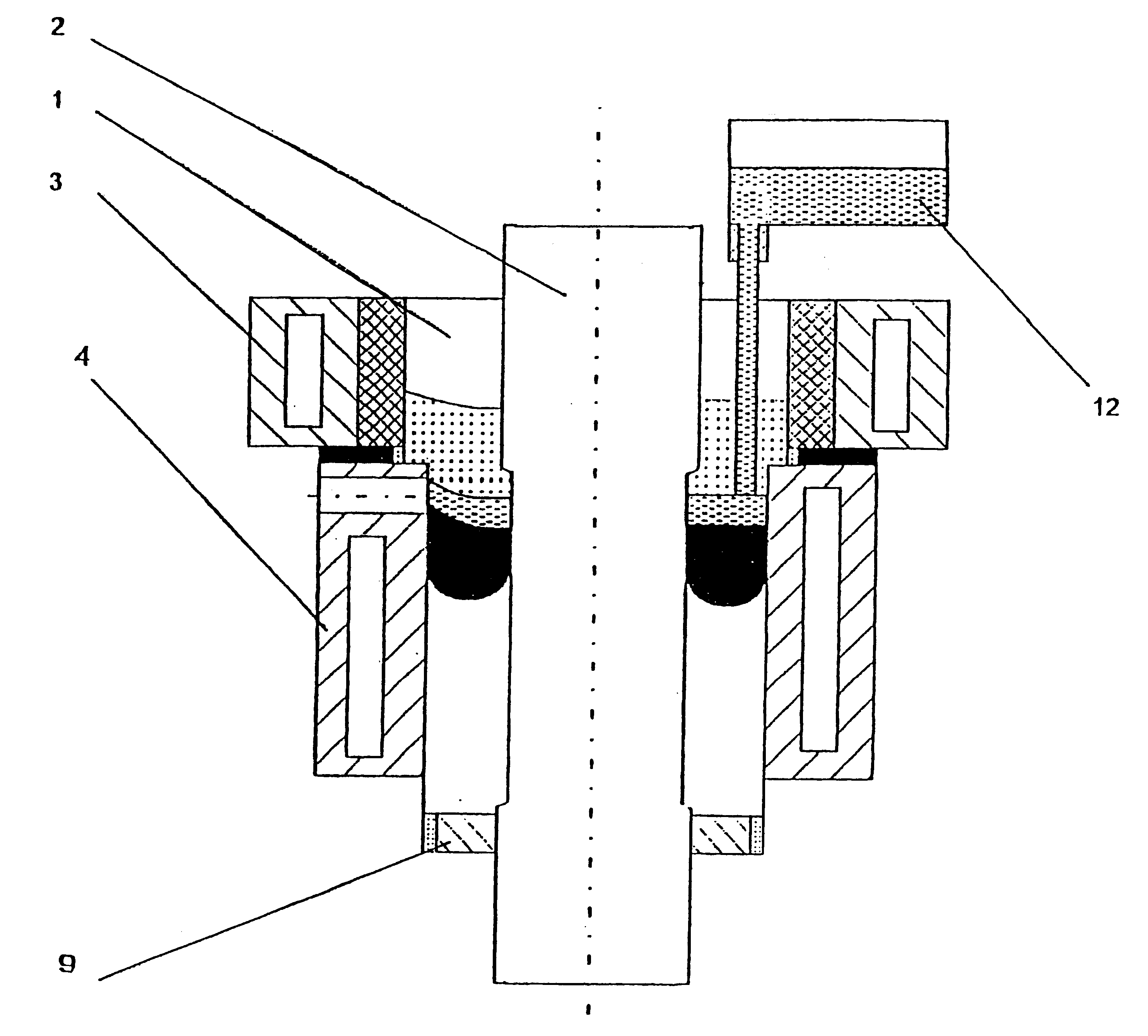
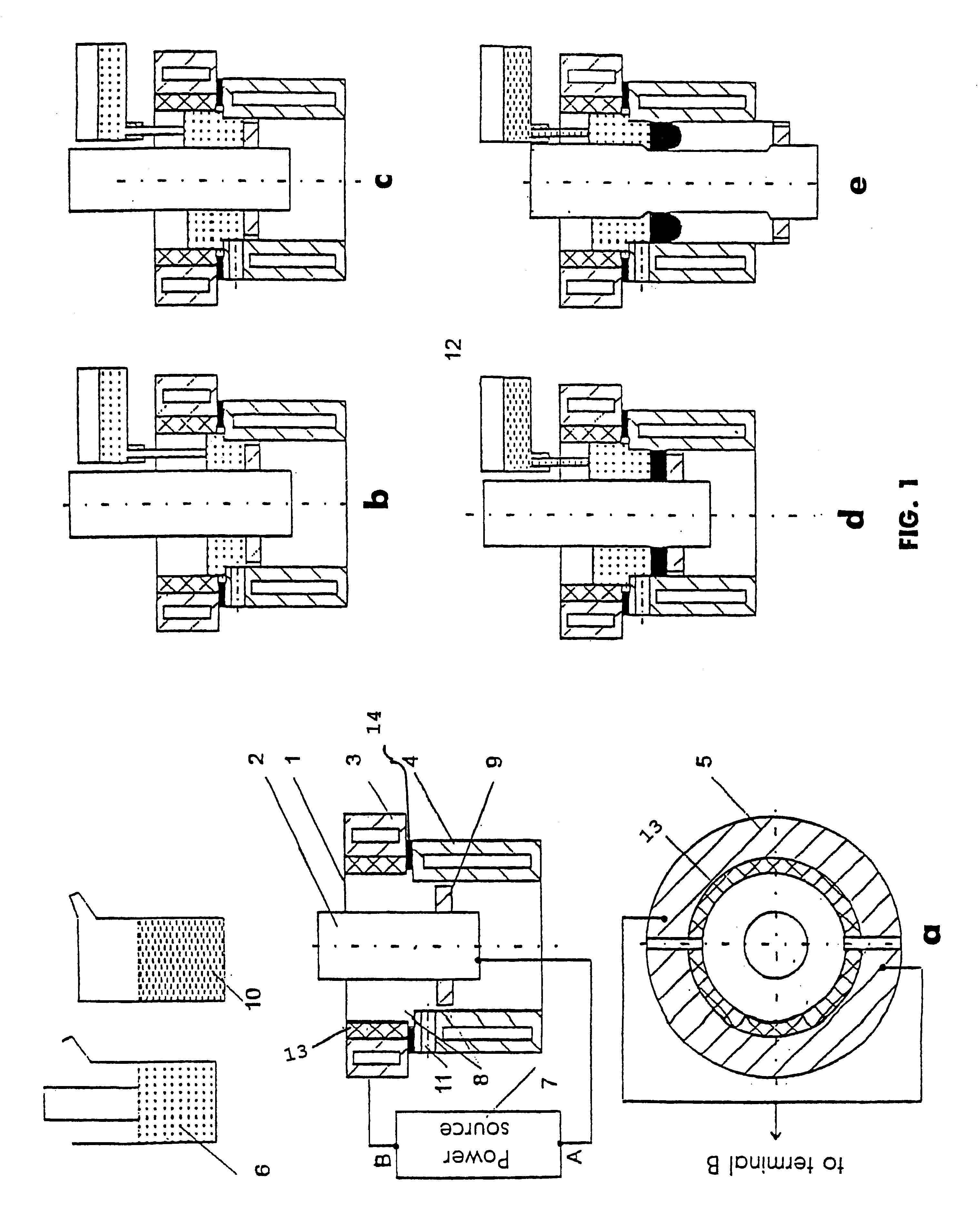
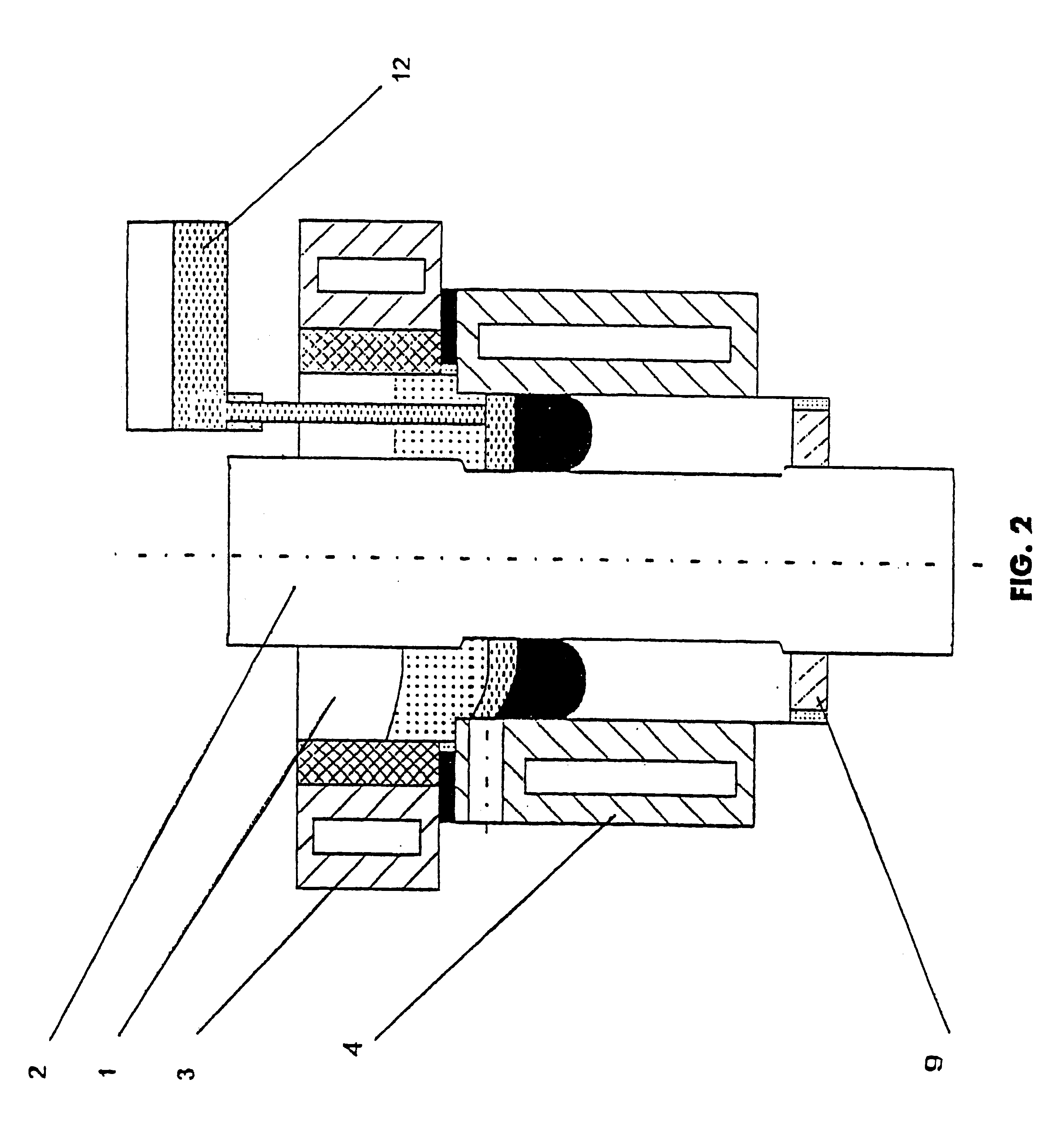
A billet to be clad 2 is mounted into a current-carrying sectional mould 1 (FIG. 1,a) and a longitudinal billet axis is brought in line with a longitudinal axis of the mould. The mould is divided in sections along the height into a current-carrying part 3 and non-current carrying forming part 4. The current-carrying upper part of the mould is also divided, as a minimum, into two sections 5. Such dividing into sections provides a uniformity in current and heat distribution. The electro-insulator (14) is provided between the divided sections 5. For protective from spark erosion, the two sections 5 have an electrically conductive lining 13.

Slag is melted in a flux melting furnace 6, for example 1 / 3CaF.sub.2 -1 / 3CaO-1 / 3Al.sub.2 O.sub.3, and poured into a mould 1 up to the level shown in FIG. 1,b. Power source 7 is now switched off. Instantaneously, the highly fluid slag fills all the air gaps 8 between the ...


PUM

PropertyMeasurementUnit
Volumeaaaaaaaaaa
Currentaaaaaaaaaa
Electric potential / voltageaaaaaaaaaa

Abstract

The disclosed process consists in filling the gap between a billet and the wall of a sectional mould with a molten slag in at least two stages. When the first portion is poured in, the gaps between the sections of the mould are filled. Once the slag in the gaps is solidified completely, voltage is supplied and the second and next portions of the slag are added. The creation of an electromagnetic field inside the mould takes place following the starting of the cladding process. The liquid metal is then added for the cladding process, which is carried out by means of the stable rotation of the slag and metal. The process can be carried out with varying levels of slag inside the current-carrying part of the mould. The billet can be preheated at the short-circuiting conditions prior to the cladding process.

Description

The invention relates to the field of metallurgy, and more specifically to the method of an electroslag cladding of elongated round-section parts mainly and can be used, in particular, in production and repair of all kinds of mill rolls, rollers of machines for a continuous casting of billets, roller tables, rollers of heating furnaces, etc.PRIOR ARTThe application of different methods of cladding for these purposes, including electroslag cladding, is widely known, allowing deposition on the above-mentioned products of a working layer made from metal or intermetallics of the chemical composition similar or different to that of the basic product.This application will not deal with the known methods of cladding using solid electrodes in the form of wire, strip, tube, etc. as a material for cladding.The most up-to-date method of cladding of the above-mentioned products is a cladding with a liquid metal which can drastically reduce the cost of the process and products and use the claddi...

Claims


Application Information

Patent Timeline
IPC IPC(8): B22D19/08
CPCB22D19/08
Inventor MEDOVAR, BORIS I.
Owner ZAKRYTOE AKTSIONERNOE OBSCHESTVO ELMET ROL GRUPPA MEDOVARA
Why Eureka
Try Eureka