Apparatus and method for dynamic modeling of an object

a dynamic modeling and apparatus technology, applied in the field of apparatus and method for dynamic modeling of objects, can solve the problems of not providing intuitive motion parameters to model the rigid and non-rigid not providing a suitable localization of the l deformation, and the utility of this class is usually limited to representing the shape and motion of the lv surfa

Inactive Publication Date: 2001-09-25
METAXAS DIMITRI
View PDF16 Cites 154 Cited by
  • Summary
  • Abstract
  • Description
  • Claims
  • Application Information

AI Technical Summary

Problems solved by technology

The main limitation of most techniques is that they do not provide intuitive motion parameters to model the rigid and non-rigid motion of the LV.
Attempts to characterize the L motion based on deformation modes, also do not provide a suitable localization of the L deformations and motion in a clinically useful manner without complex post-processing, due to the global definition of each modal deformation.
Moreover, most techniques ignore the twisting or wringing motion of the LV known to occur during systole.
The utility of this class, however, is usually limited to representing LV surface shape and motion because the L motion cannot be captured entirely with surface models.
Such modalities typically cannot provide explicit, time-varying 3D motion of material data points from to the LV.
However, the finite element representation does not directly lend itself to an understanding of the underlying kinematics in a clinically useful way.
The physical interpretation of these parameters can be difficult.
Although the implantation methods have been used for the LV motion analysis, and provide accurate localization, the invasive nature of the procedures does not allow a sufficient number of markers to be implanted for describing the LV geometry.
Moreover, it poses the potential problem of local myocardium property alteration due to the introduction of foreign objects.
When the blood supply is severely obstructed due to arterial occlusion, the tracing of the feature points around the region can be very difficult to achieve.
One drawback of current MR tagging techniques, is that the tracking is possible only during systole or diastole at one time (i.e., not for a complete heart cycle), due to the decay of the magnetization signal over time.

Method used


Image

  • Apparatus and method for dynamic modeling of an object
  • Apparatus and method for dynamic modeling of an object
  • Apparatus and method for dynamic modeling of an object

Examples


Embodiment Construction

Accurately estimating the volumetric shape, motion and deformations of a deformable object, e.g., the left ventricle (LV), and presenting the estimating of these properties in a readily understandable manner is generally unavailable with existing imaging techniques. For example conventional cardiac imaging methods including MRI still have many limitations, such as a lack of explicit data correspondence between temporal image data frames, and insufficient resolution of the extracted data. In addition, most of the existing models for the analysis of the certain LV shape and motion are based on the use of parameters that are either too complex or too few to be used by a clinician.

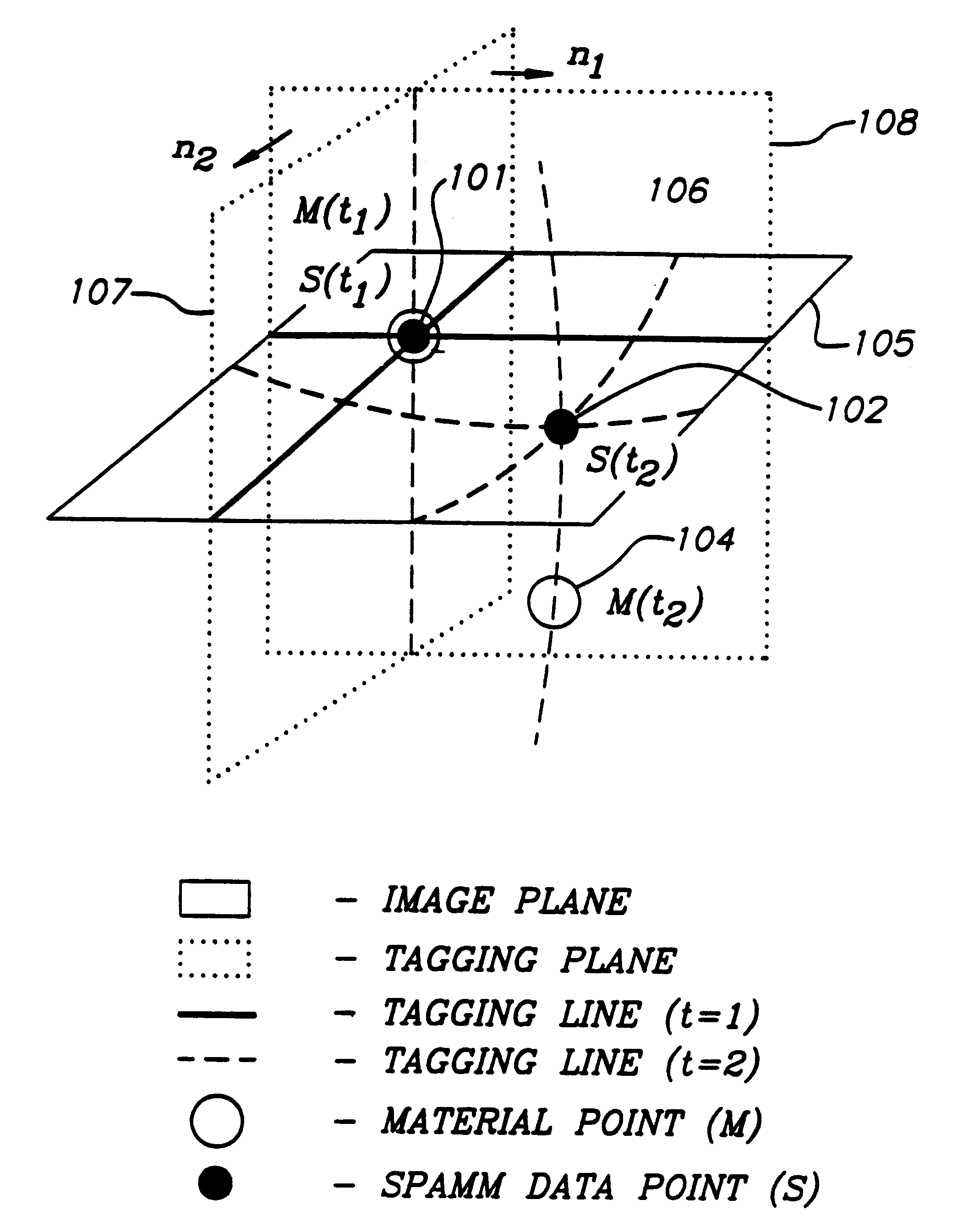
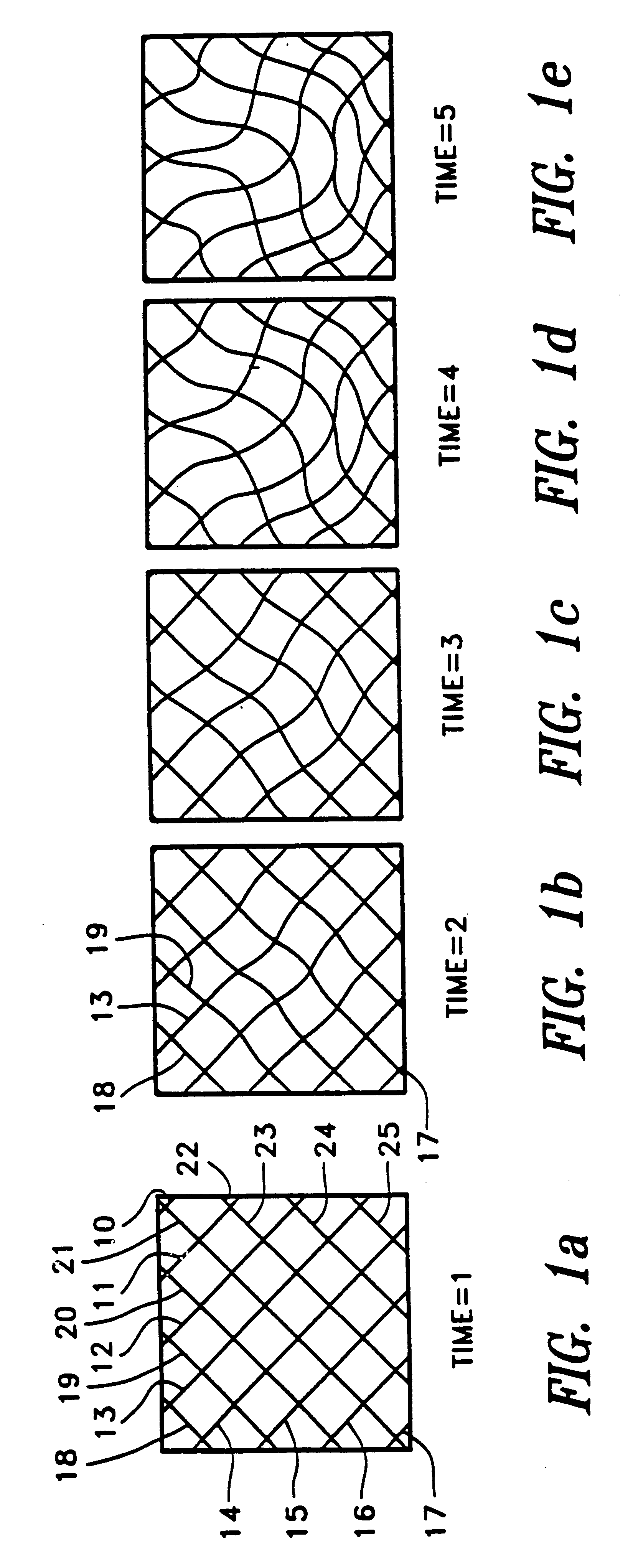
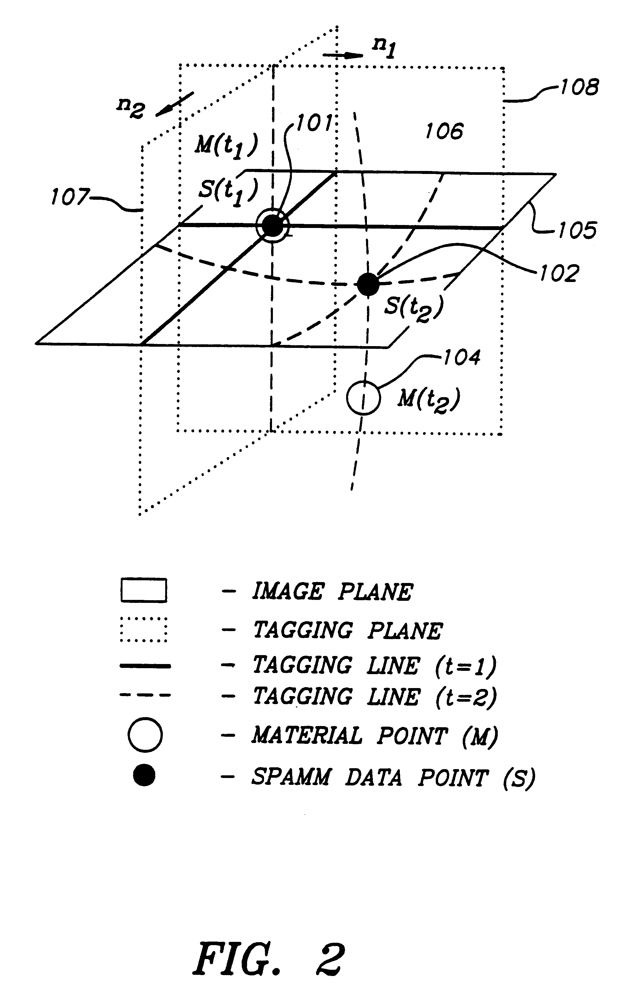
A magnetic resonance imaging (MRI) technique based on magnetic tagging employing spatial modulation of magnetization (MRI-SPAMM) has been developed for imaging of an object's regional movement, e.g. heart wall motion. This fast, non-invasive technique can be useful in the analysis of heart wall motion because ...


PUM


Abstract

A method and apparatus for dynamic modeling of an object having material points. The method includes receiving signals from a sensor which correspond to respective material points; providing a volumetric model, having functions as parameters, representative of the object; and adapting the parameters to fit a changing model shape. This method of dynamic shape modeling dynamic motion modeling or both includes shape estimation and motion analysis. The apparatus includes a signal processor for receiving signals from a sensor, a second signal processor for providing a volumetric model having functions as parameters representative of the object and a third signal processor for receiving sensed signals and adapting the model and providing a dynamic representation.

Description

The invention relates to an apparatus and method for object modeling, particularly to dynamic modeling of an object, and most particularly to dynamic modeling, shape estimation, and motion analysis of an object having material points therein, for example, a human heart.BACKGROUND OF THE ARTMany model-based approaches to the analysis of the complicated motion of an object, such as the left ventricle (LV) of the heart, and the quantification of its measured deformation, exist. Simple analytical models like spheres, ellipsoids or cylinders often are used. For example, Beyar and Sideman constructed a mechanical model where the LV is modeled as a nested-shell spheroidal to explain the effect of twisting motion; Arts (1982) used a thick-walled cylinder composed of eight concentric cylinder shells to describe the LV deformation; Kim et al. used a thick-walled ellipsoidal model for the computation of the LV wall stress, and a truncated ellipsoidal model for simulation of regional stress; Az...

Claims


Application Information

Patent Timeline
Patent Type & Authority Patents(United States)
IPC IPC(8): G06T17/20G06T17/00
CPCG06T17/20G06T17/00
Inventor METAXAS, DIMITRI
Owner METAXAS DIMITRI
Why Eureka
Try Eureka