Closed loop single mixed refrigerant process

Inactive Publication Date: 2001-10-02
BLACK & VEATCH HLDG
View PDF3 Cites 71 Cited by
  • Summary
  • Abstract
  • Description
  • Claims
  • Application Information

AI Technical Summary

Problems solved by technology

Many sources of natural gas are located in remote areas which are not conveniently available to any commercial markets for the gas.
LNG refrigeration systems are expensive because considerable refrigeration is necessary to liquefy the natural gas.
Since refrigeration equipment represents such a significant part of the LN

Method used


Image

  • Closed loop single mixed refrigerant process
  • Closed loop single mixed refrigerant process
  • Closed loop single mixed refrigerant process

Examples


Embodiment Construction

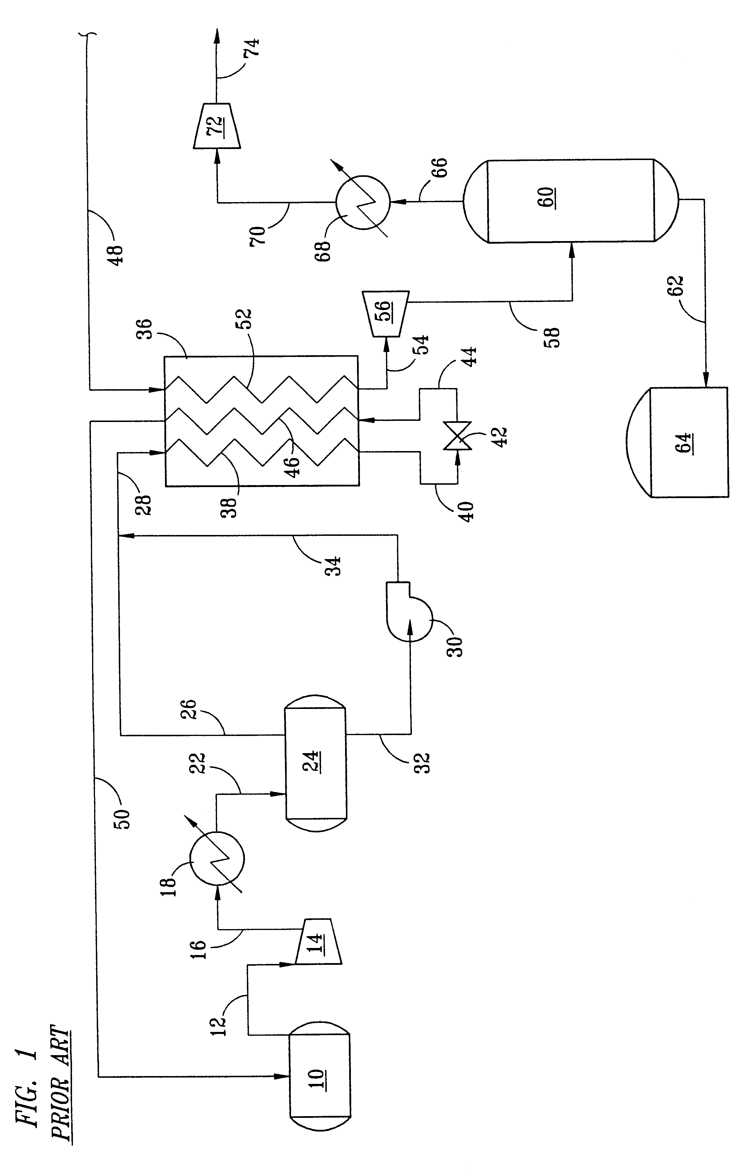
Comparative processes are shown in FIGS. 3 and 4. The process shown in FIG. 3 is a prior art process as shown in FIG. 1. FIG. 3 shows the process in somewhat greater detail for the natural gas recovery section. A pump 82 is shown in line 62 and a fuel gas treating section 84 is shown schematically with the refrigerant treatment section being shown schematically as 86.

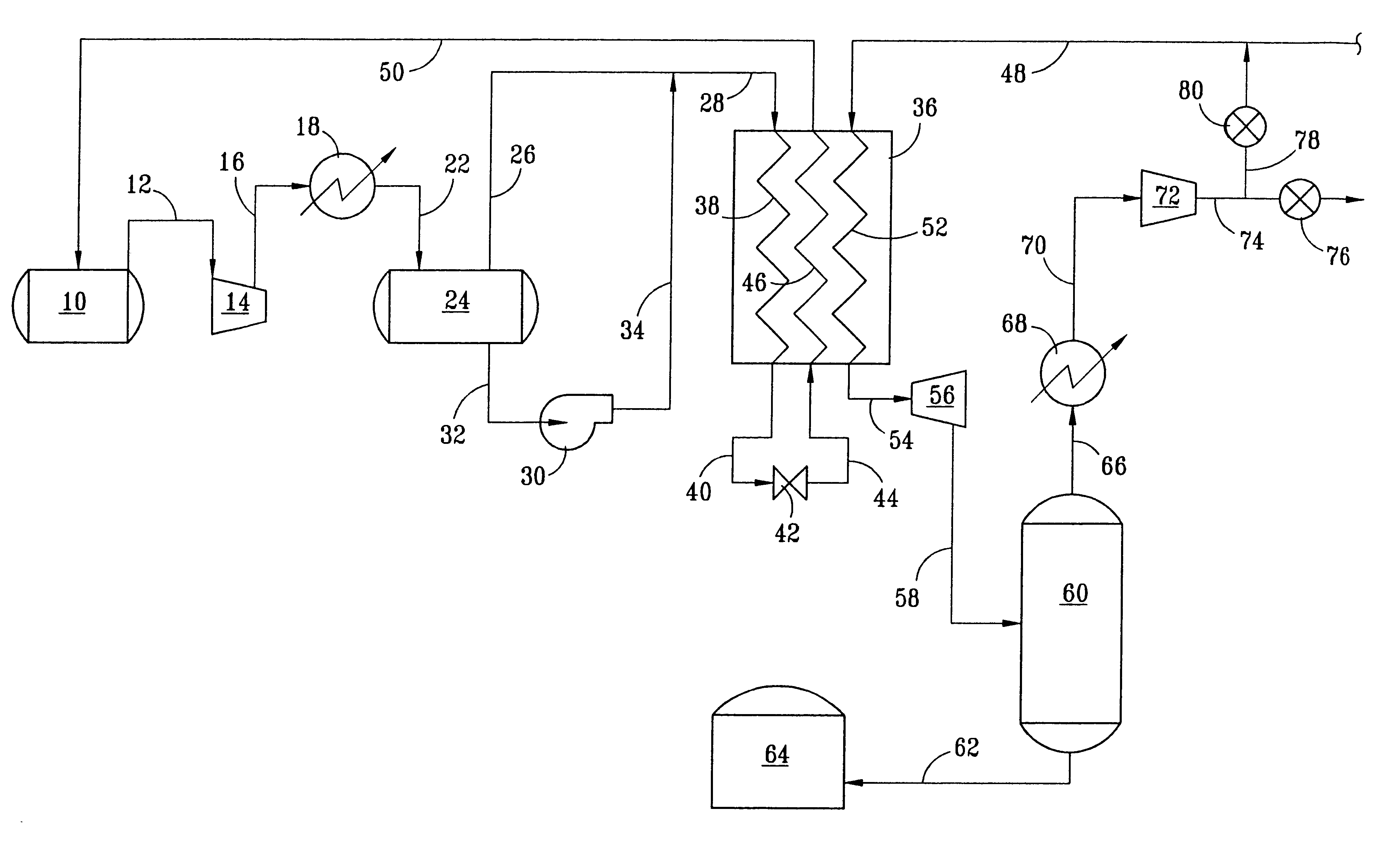
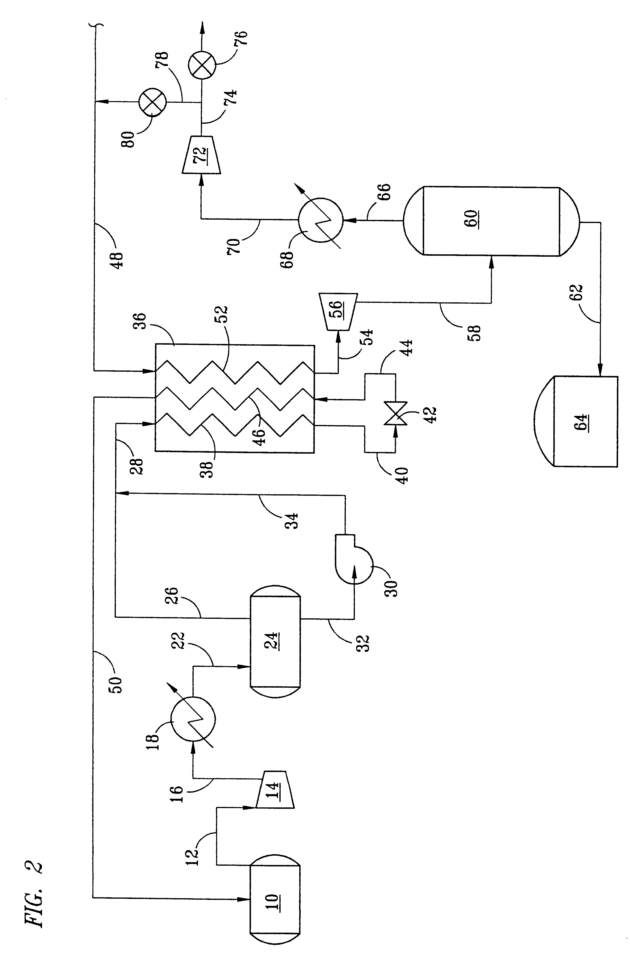
FIG. 4 is a comparable, more detailed description of the process of the present invention.

A comparative embodiment of the process shown in FIG. 3 and the process shown in FIG. 4 are shown in some detail in Table 1.

It will be noted that the temperature in line 54 in the embodiment shown in FIG. 4 has been increased. Natural gas is still produced in line 62 at the same temperature and pressure. Similarly, fuel gas is still produced in line 74 at the same temperature and pressure. In the embodiment shown, the same quantity of liquefied natural gas is produced, but the power requirements for the operation of the overall pro...


PUM


Abstract

A closed loop single mixed refrigerant process and system wherein the process efficiency is increased by increasing the temperature of liquefied material produced in a heat exchange refrigeration zone and thereafter cooling the liquefied material by flashing a portion of the liquefied material to produce a cooler liquefied material and a flash gas a portion of which is recycled to the heat exchange refrigerator. The process and system provide increased process efficiency and flexibility.

Description

1. Field of the InventionThis invention relates to a closed loop single mixed refrigerant process wherein the capacity of the process can be increased by adjusting the temperature of the liquefied fluid material produced in the process.2. Brief Description of the Prior ArtBecause of its clean burning qualities and convenience, natural gas has been widely used in recent years. Many sources of natural gas are located in remote areas which are not conveniently available to any commercial markets for the gas. When pipelines are unavailable for transportation of the natural gas to a commercial market, the produced natural gas is often processed into a liquefied natural gas (LNG) for transport to market. One of the distinguishing features of an LNG plant is the large capital investment required for the plant. The liquefaction plant is made up of several basic systems including gas treatment to remove impurities, liquefaction, refrigeration, power facilities and storage and ship loading fa...

Claims


Application Information

Patent Timeline
IPC IPC(8): F25J1/00F25J1/02
CPCF25J1/0022F25J1/0042F25J1/0052F25J1/0219F25J1/0254F25J1/0262F25J2220/62F25J2235/60F25J2245/02F25J2290/32
Inventor HOFFART, SHAWN D.PRICE, BRIAN C.
Owner BLACK & VEATCH HLDG
Why Eureka
Try Eureka