Solid immersion lens structures and methods for producing solid immersion lens structures

a technology of solid immersion lens and structure, which is applied in the direction of lenses, instruments, other domestic objects, etc., can solve the problems of complex manufacturing process, long polishing time, and inability to perfect,

Inactive Publication Date: 2001-10-09
CALIFORNIA INST OF TECH
View PDF6 Cites 152 Cited by
  • Summary
  • Abstract
  • Description
  • Claims
  • Application Information

AI Technical Summary

Problems solved by technology

A problem with the SIL technology is the complexity of its manufacture.
For example, a polished glass sphere provided with a sequence of progressively finer alumina powders, requires a polishing time typically of many hours.
Furthermore, the result is not perfect, and

Method used


Image

  • Solid immersion lens structures and methods for producing solid immersion lens structures
  • Solid immersion lens structures and methods for producing solid immersion lens structures
  • Solid immersion lens structures and methods for producing solid immersion lens structures

Examples


Embodiment Construction

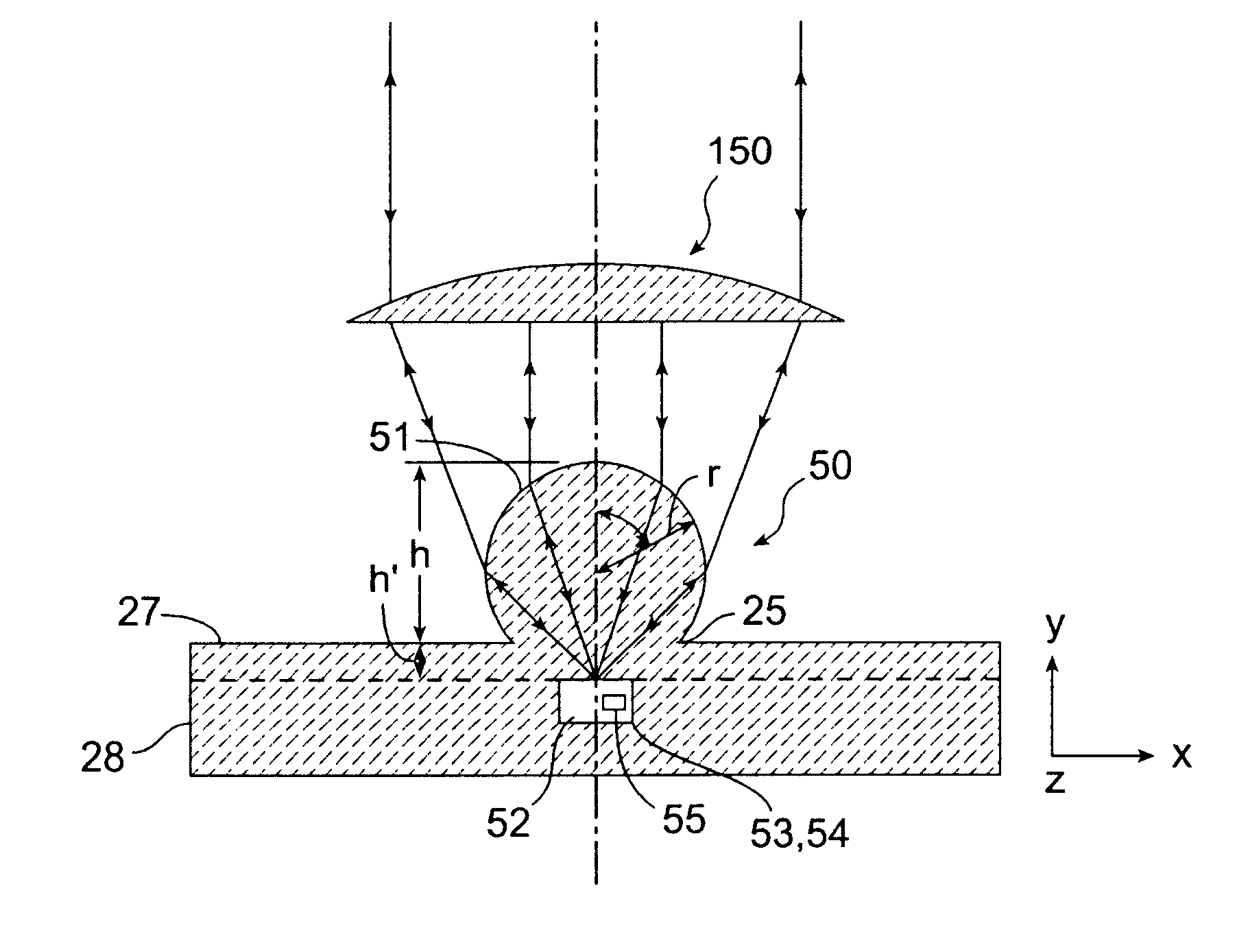
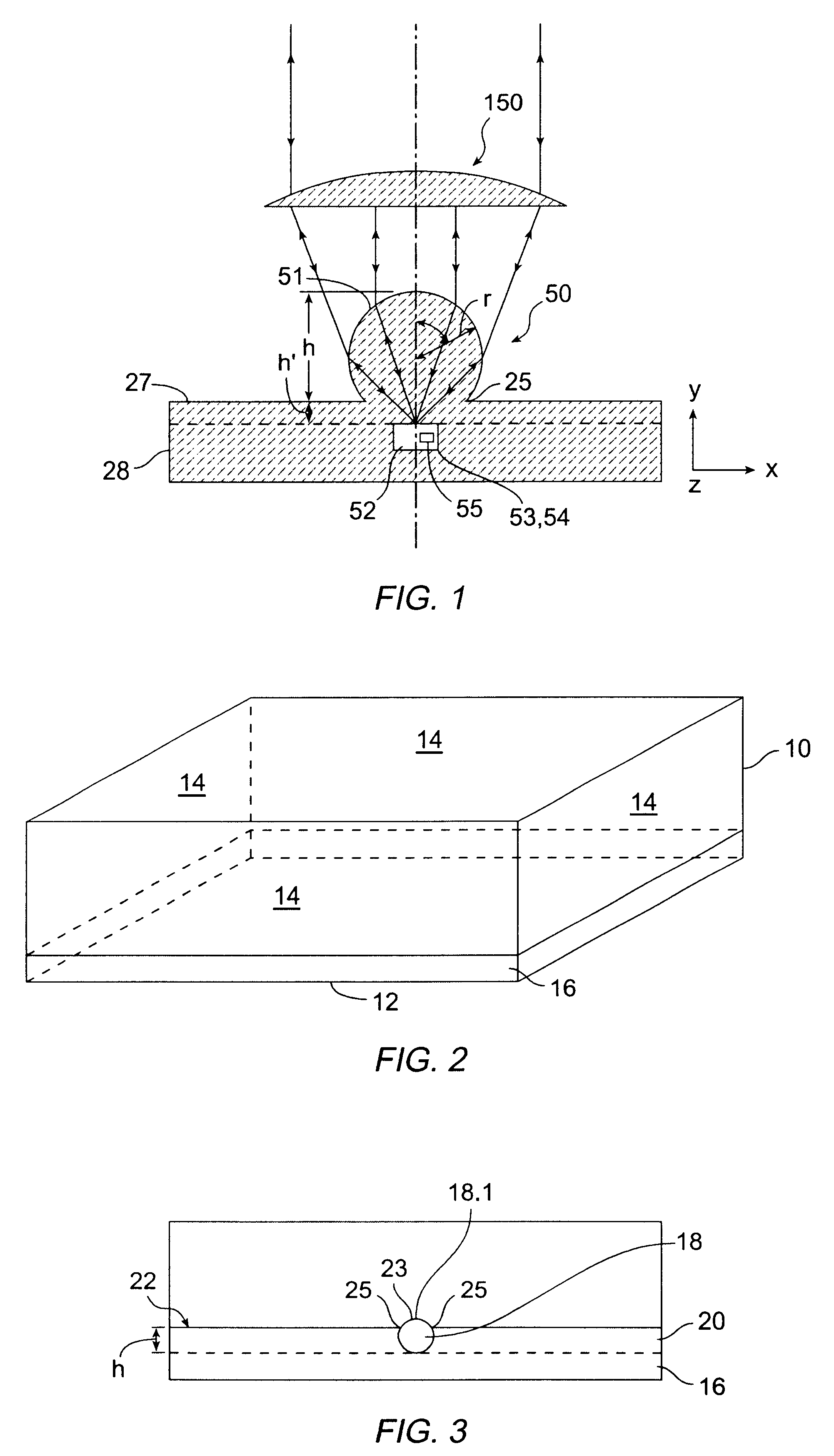
In order to understand the invention, it is helpful to define the terms associated with a solid immersion lens SIL structure 50 as it might be used in a device such as a microscope, spectroscope or cytometer. FIG. 1 illustrates the functioning of a solid immersion lens, with indication of the parameters used to describe the structure and operation. A solid immersion lens portion 51 comprises a sphere of radius r and index of refraction n.sub.s. It is disposed at a highest height h above a surface 27 of a body portion 28 so that a boundary margin 25 is formed which is narrower in diameter than the diameter of the lens portion 51. An observation region 52 is provided at a distance h' from the surface 27. Samples are placed in the region for observation according to the intended application, such as microscopy, spectroscopy or cytometry. Also shown with the structure 50 is a collection / collimating lens 150. The spherical structure and collection configuration admits to construction of ...


PUM

PropertyMeasurementUnit
Adhesion strengthaaaaaaaaaa
Moldableaaaaaaaaaa
Dimensionaaaaaaaaaa

Abstract

A solid immersion lens structure is a translucent pliant elastomer cast to a desired shape and smoothness. A method for construction of a solid immersion lens structure includes providing a mold defining a lens shaped cavity in which a solid immersion lens is cast, casting a translucent liquid elastomeric material into the lens cavity, permitting the elastomeric material to set to form the solid immersion lens portion and removing the solid immersion lens portion from the mold. A specific material for use as the solid immersion lens is a translucent silicone elastomer of a refractive index greater than n=1.4, such as General Electric RTV 615.

Description

BACKGROUND OF THE INVENTIONThe present invention relates to solid immersion lens (SIL) structures and in particular to techniques for constricting SIL structures, as well as selected applications of such structures.Due to the limitations on resolutions obtainable with conventional optical lenses for applications such as microscopy, techniques have been developed to decrease the Rayleigh limit on transverse resolution .delta.. The Rayleigh limit is given by (.delta.=0.82.lambda. / (NA) where .lambda. is the wavelength and NA is the numerical aperture of the focusing, objective (NA=n sin (.theta.), where n is the refractive index of the medium, and .theta. is the angle between the outermost rays focusing on the sample and the optical axis)Coherent light such as laser light can be used to precisely control the wavelength of illumination .lambda.. One way to decrease the transverse resolution is to increase the index of refraction of the optical medium, Such as by use of oil-immersion mic...

Claims


Application Information

Patent Timeline
IPC IPC(8): B29C39/02B29C39/36B29C39/22B29C33/48B29C33/50B29D11/00G02B21/00G02B3/00B29K19/00B29K83/00
CPCB29C33/50B29C39/02B29C39/021B29C39/36B29D11/00394B29D11/00432G02B3/00G02B21/00Y10S359/90
Inventor LEGRAND, OLIVIERQUAKE, STEPHEN R.
Owner CALIFORNIA INST OF TECH
Why Eureka
Try Eureka