Vehicle control system and method

a rearview mirror and automatic technology, applied in the field of vehicle control system and method, can solve the problems of inaccurate forward facing or "ambient" light sensor, increased mirror sensitiveness, and even "locking"

Inactive Publication Date: 2001-10-16
DONNELLY CORP
View PDF92 Cites 463 Cited by
  • Summary
  • Abstract
  • Description
  • Claims
  • Application Information

AI Technical Summary

Problems solved by technology

These mirrors suffered from various problems, however, including the problem that these mirrors would become increasingly sensitive and even "lock-up" in their minimum reflectance level or state as the driver encountered significantly higher light levels in town or city driving.
These arrangements, however, also had problems.
In some of these mirrors the forwardly facing or "ambient" light sensor was inaccurate because it did not correctly measure ambient light levels since it did not include light generally rearward of the mirror or vehicle.
prior art two-sensor type systems generally provided improved performance over prior art single-sensor type systems but were also more complex and costly.
Matching photocells such as photoresistors, however, generally involves complex, expensive and time consuming operations and procedures.
Both the prior art single-sensor and two-sensor type mirrors presented additional problems when they were also used to control the exterior side view mirrors.
The situation is further complicated with multi-lane traffic because each of the mirrors reflects different light levels caused by the headlights of the vehicles which are following, passing or being passed.
This approach is not satisfactory, however, because it reduces system reliability and increases complexity and cost.
These prior mirror systems generally have the same problems as the other single-sensor type mirrors.
Thus, as the number of vehicle lighting options has increased, it has become more complex for the driver to determine the appropriate vehicle lighting configuration and to operate or control the vehicle lighting systems.
Finally, unauthorized vehicle intrusion for the purpose of stealing the vehicle or its contents is a significant problem.
As is known, existing intrusion detection systems for vehicles use sensor technologies that have various limitations, including the problem of false triggering.
The proliferation of separate automatic rearview mirror systems and vehicle intrusion detection systems is also costly.
Even with such anti-theft systems, recovered stolen vehicles typically provide little or no evidence of the vehicle thief.

Method used


Image

  • Vehicle control system and method
  • Vehicle control system and method
  • Vehicle control system and method

Examples


Embodiment Construction

I. The Automatic Rearview Mirror System

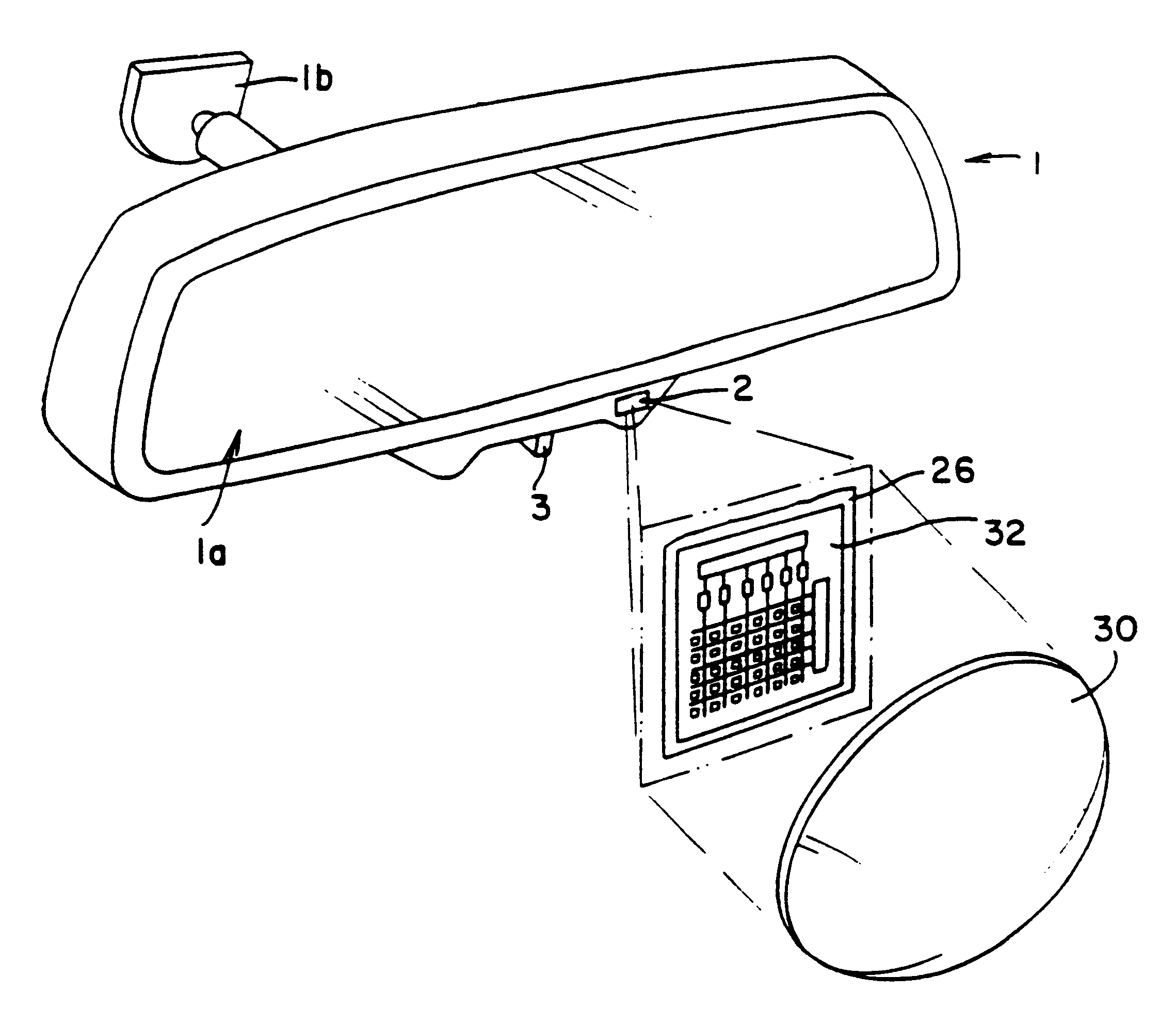
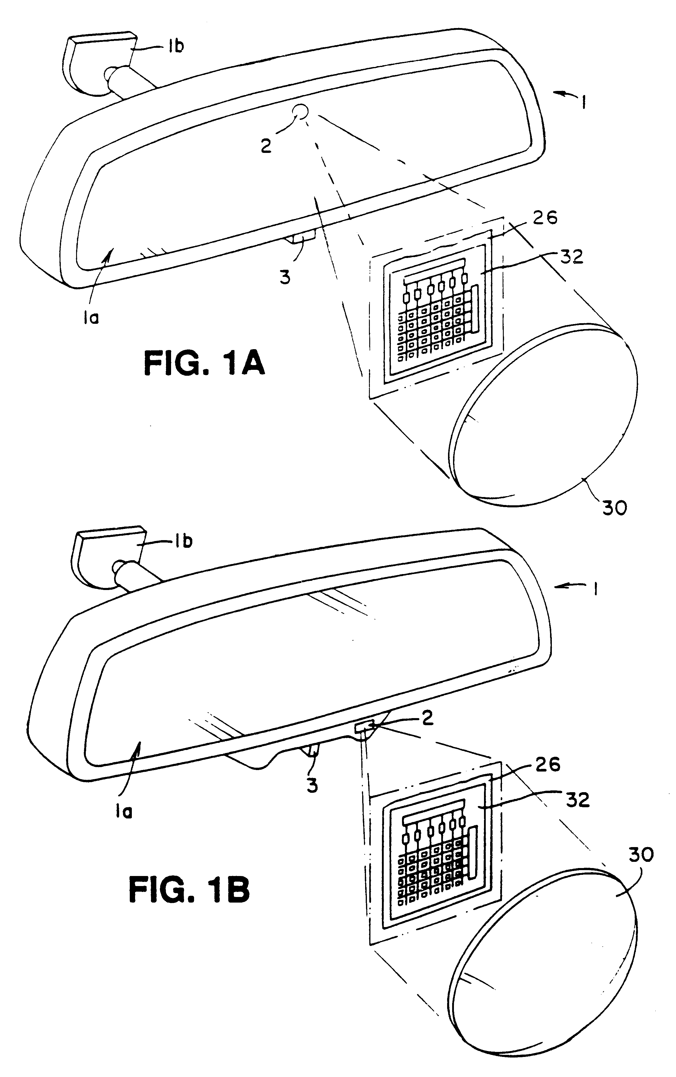
FIG. 1A illustrates an automatic rearview mirror 1 comprising a variable reflectance mirror element 1a and a single rearwardly facing photosensor 2. The photosensor 2 is mounted facing rearwardly of the rearview mirror 1 so that its field of view encompasses an area comprising a rear window area and at least a portion of either or both side window areas. Also shown is a switch 3 to allow a driver to manually control several possible mirror functions, such as an on-off control switch, a sensitivity adjustment and a force-to-day or a force-to-night switch (i.e., forced maximum or minimum reflectance levels, respectively). An expanded view of the photosensor 2, which is preferably located in an upper center area of the variable reflectance mirror element 1a as shown, shows a light sensing and logic circuit 26 comprising a photosensor array 32 and a logic and control circuit 34 (which is not shown in FIG. 1A but is shown in FIG. 6 as discussed belo...


PUM


Abstract

A vehicle control system and method includes structure and steps for capturing an image of a front seat of the vehicle and outputting image data corresponding thereto. A processor is provided which receives the image data output form the imaging device, compares the received image data with stored image data, and outputs a vehicle equipment control signal based on the comparison. Preferably, the vehicle equipment control signal controls one or more of airbag activation, mirror reflectance, vehicle lights activation, and vehicle intruder alarms. Preferably, the imaging device comprises a single chip camera disposed adjacent the vehicle rearview mirror.

Description

1. Field of the InventionThis invention relates to an automatic rearview mirror system for automotive vehicles which automatically changes reflectance level in response to glare causing light, and more particularly relates to an improved automatic rearview mirror system using only a rearwardly facing sensor. This invention further relates to an automatic rearview mirror and vehicle interior monitoring system for automotive vehicles which also monitors a vehicle interior or compartment. This invention further relates to an automatic rearview mirror and vehicle interior monitoring system for automotive vehicles which may also be used as a vehicle intrusion detection system or as a compartment image data storage system. This invention further relates to an automatic rearview mirror and a vehicle lighting control system using an image sensor, such as a photosensor array.2. Description of Related ArtAutomatic rearview mirrors and mirror systems have been devised for varying the reflectan...

Claims


Application Information

Patent Timeline
Patent Type & Authority Patents(United States)
IPC IPC(8): B60N2/00B60S1/08B60Q1/04B60R1/00B60Q1/14B60R11/04B60Q1/50B60Q1/08B60Q1/52B60R1/12B60R11/00B60R1/08H04N7/18B60R21/01B60R1/04B60R1/06B60R21/015H04N13/243
CPCH04N7/183B60S1/0844B60R1/088B60N2/002G01J1/4204B60R1/00H04N13/0239H04N7/18B60R1/12B60Q1/04B60S1/0822H04N5/374H04N7/181G06T7/0022B60R11/04B60S1/0885B60Q1/1423B60Q1/143B60R21/01538B60R1/04G01J1/4228B60R2300/30H04N2013/0081B60Q2300/43B60R2001/1253G06T2207/10016B60R2300/8073G06T2207/30252B60Q2300/312B60Q2400/30B60Q2300/42B60R2300/8006B60R2300/8066B60R2001/1223B60Q2300/3321G06T2207/30268B60R2300/8026B60R2300/103B60R2300/8093B60Q2300/41B60Q2300/314B60Q2300/052B60R2300/8046B60Q2300/21G06T7/97H04N13/239H04N13/243H04N23/63H04N25/443H04N25/76
Inventor SCHOFIELD, KENNETHLARSON, MARK
Owner DONNELLY CORP
Why Eureka
Try Eureka