Wireless coiled tubing joint locator

Inactive Publication Date: 2001-10-23
HALLIBURTON ENERGY SERVICES INC
View PDF6 Cites 49 Cited by
  • Summary
  • Abstract
  • Description
  • Claims
  • Application Information

AI Technical Summary

Problems solved by technology

However, no matter how accurate the coiled tubing surface measuring device is, true depth measurement is flawed due to effects such as coiled tubing stretch, elongation from thermal effects, sinusoidal and helical buckling, and a variety of often unpredictable deformations in the length of coiled tubing suspended in the wellbore.
The use of such production tubing string end locator tools involve a number of problems.
The most common problem is that not all wells include production tubing strings and only have casing or are produced open hole.
Thus, in those wells there is not production tubing string on which the tool can catch while moving upwardly.
Another problem associated with the lower end of the production tubing string as a locator point is that the tubing end may not be accurately located with respect to the producing zone.
Tubing section lengths are tallied as they are run in the well and mathematical or length measurement errors are common.
Even when the tubing sections are measured and tallied accurately, the joint and tally log can be inaccurate with respect to where the end of the tubing string is relative to the zone of interest.
Yet another problem in the use of production tubing in locator t

Method used


Image

  • Wireless coiled tubing joint locator
  • Wireless coiled tubing joint locator
  • Wireless coiled tubing joint locator

Examples


first embodiment

OPERATION OF THE FIRST EMBODIMENT

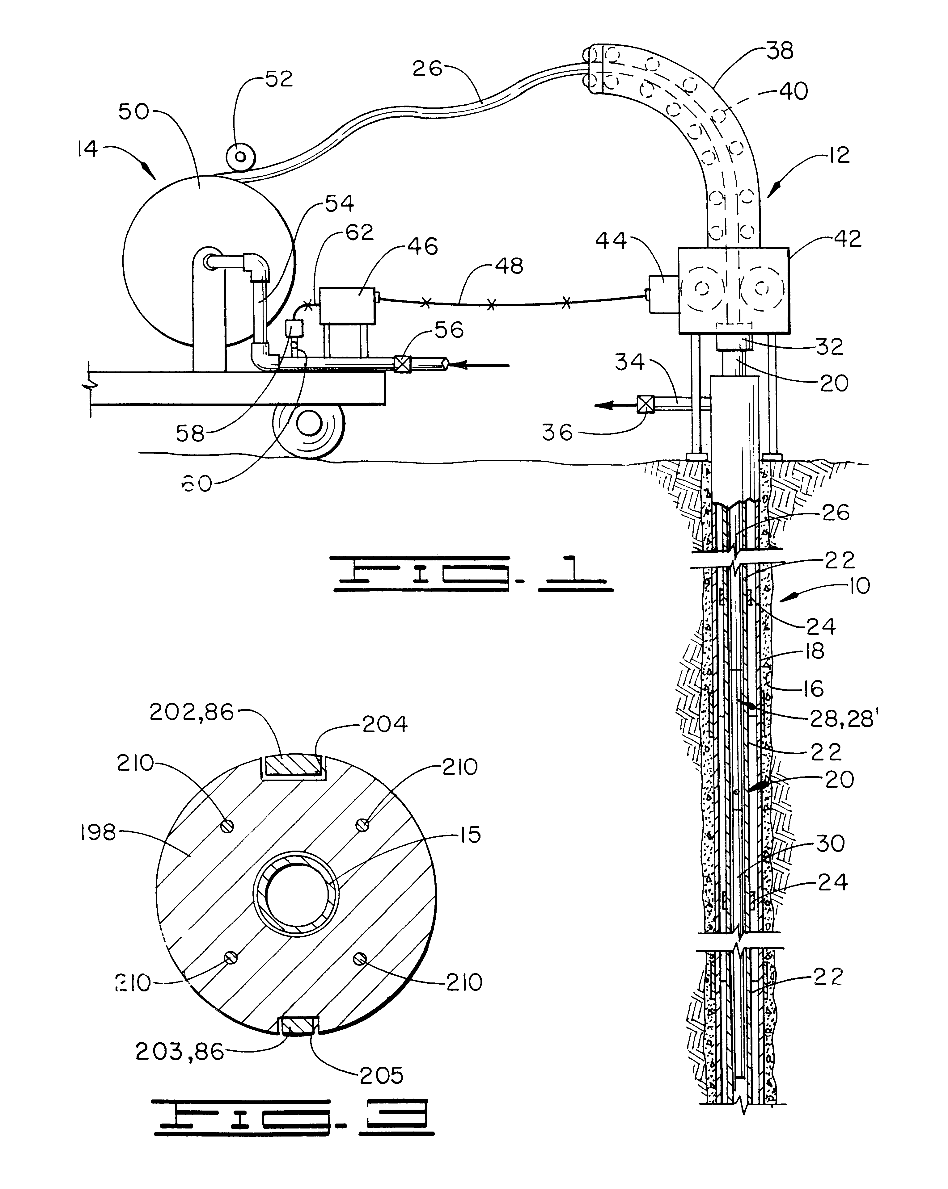
In operation, first embodiment joint locator 28 is attached to coiled tubing 26 at threaded opening 124 as previously described, and a well tool 30 is connected below joint locator 28. Coiled tubing 26 is injected into well 10 and may be raised within the well using injector 12 in the known manner with corresponding movement of joint locator 28. Thus, joint locator 28 may be raised and lowered within production tubing string 20. As joint locator 28 passes through a pipe joint 24, electromagnetic coil assembly 220 senses the increased mass of the pipe joint.

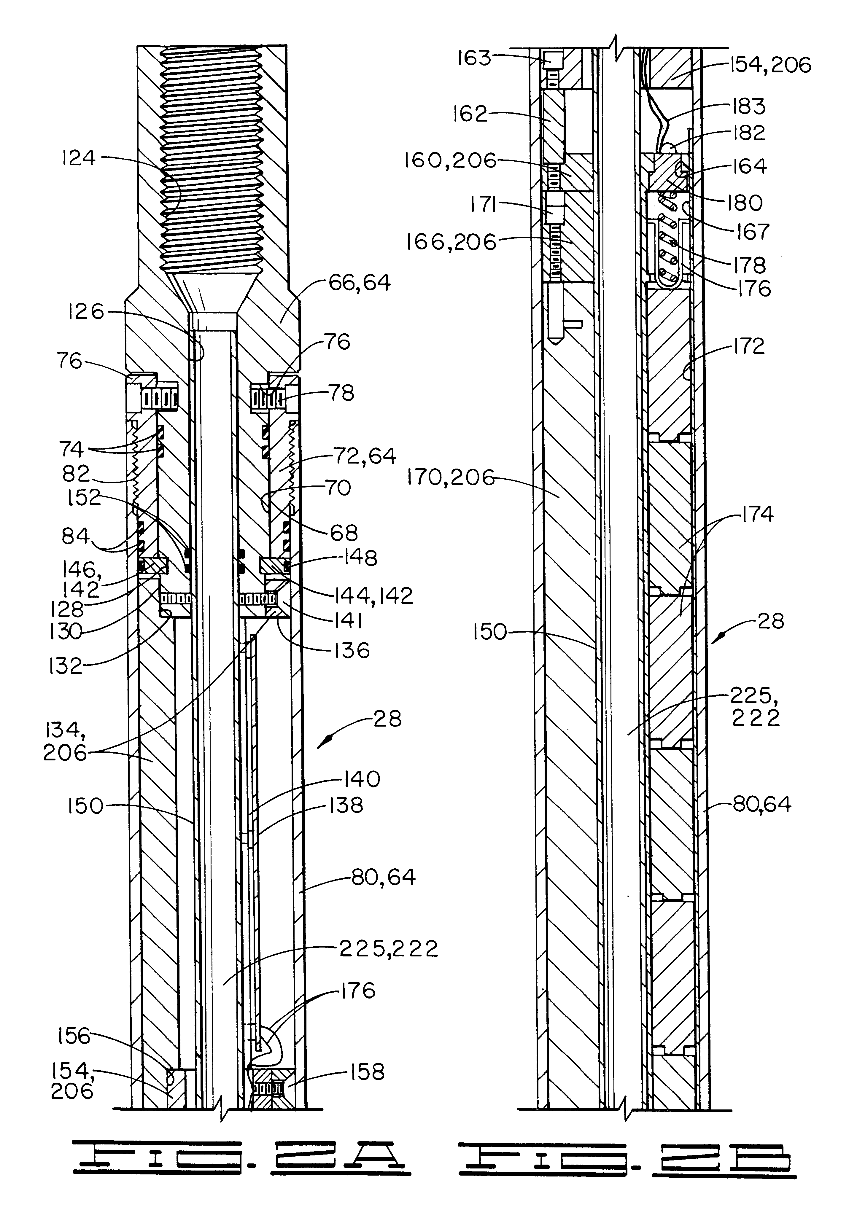
Referring to FIG. 4, a flow chart of an electrical circuit 390 for joint locator 28 is shown and will be understood by those skilled in the art. Most of electrical circuit 390 is on printed circuit board 138. Power for circuit 390 is provided by batteries 174, and coil assembly 220 and solenoid valve 286 are also part of the circuit.

To minimize the consumption of power, circuit 390 includes a time ...

second embodiment

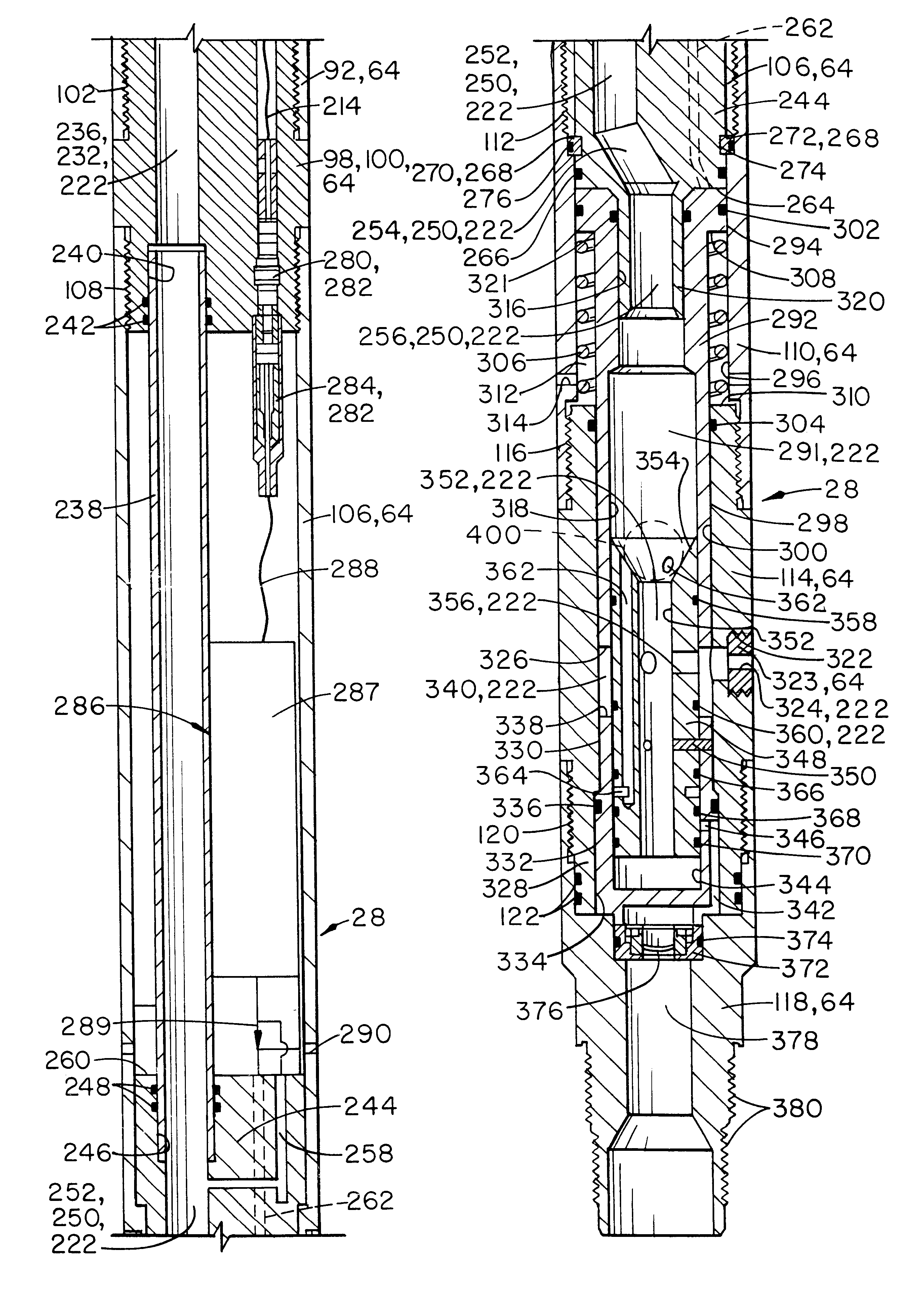
Referring now to FIG. 5, second embodiment joint locator 28' is shown. Second embodiment joint locator 28' includes the same outer housing 64 of first embodiment joint locator 28. At the lower end thereof, shown in FIG. 5, outer housing 64 thus again comprises circulating sub 114 attached to a bottom sub 118 at threaded connection 120. O-rings 122 provide sealing engagement therebetween.

An insert 400 is disposed in circulating sub 114. Insert 400 has a first outside diameter 402 sized to fit within second bore 318 of piston 292. A sealing means, such as an O-ring 404, provides sealing engagement between insert 400 and piston 292. Insert 400 also includes a second outside diameter 406 sized to fit within first bore 300 of circulating sub 114 and a larger third outside diameter 408 sized to fit within second bore 334 of circulating sub 114.

Insert 400 defines an upper central opening 410 therethrough, forming part of flow passageway 222. One or more transversely extending ports 412, al...


PUM


Abstract

A wireless coiled tubing joint locator for locating joints or collars in a production tubing string. An electromagnetic coil assembly or giant magnetoresistive digital field sensor senses the increased mass of a pipe joint, and provides a signal to an electric circuit which generates a signal received by a pilot solenoid valve. The solenoid valve momentarily opens a pilot passageway which activates a piston to close a circulation port in the joint locator, resulting in an increase in a surface pressure reading observable by the operator. In one embodiment, a rupture disk is provided so that pressure cannot be applied to any downhole tool below the joint locator prematurely. A seat sleeve prevents premature communication of fluid to the rupture disk but can be opened by dropping a ball into the joint locator. A second embodiment may be used for either logging or washing operations or both. The electronic circuit can provide a selected one of a plurality of time delays. A fixed test period in the circuit delays activation of the time delay so that the joint locator may be tested before it is run into the well. The electric circuit and power supply are provided in a removable case.

Description

1. Field of the InventionThe present invention relates generally to subterranean pipe string joint locators, and more particularly, to a joint locator for positioning on a well tool connected to coiled tubing in a well and which has a pressure differential actuated piston controlled by a pilot solenoid valve.2. Description of the Prior ArtIn the drilling and completion of oil and gas wells, a wellbore is drilled into the subterranean producing formation or zone of interest. A string of pipe, e.g., casing, is typically then cemented in the wellbore, and a string of additional pipe, known as production tubing, for conducting produced fluids out of the wellbore is disposed within the cemented string of pipe. The subterranean strings of pipe are each comprised of a plurality of pipe sections which are threadedly joined together. The pipe joints, also often referred to as collars, are of an increased mass as compared to other portions of the pipe sections.It is often necessary to precise...

Claims


Application Information

Patent Timeline
IPC IPC(8): E21B23/04E21B23/00E21B34/00E21B34/06E21B21/00E21B21/10E21B47/00E21B34/14E21B47/09
CPCE21B21/103E21B23/04E21B34/063E21B34/066E21B34/14E21B47/04E21B47/0905E21B47/091E21B47/092E21B47/095
Inventor CONNELL, MICHAEL L.TUCKER, JAMES C.HOWARD, ROBERT G.
Owner HALLIBURTON ENERGY SERVICES INC
Why Eureka
Try Eureka