Three level inverter apparatus

a technology of inverter and inverter, which is applied in the direction of dc-ac conversion without reversal, dc-ac circuit to reduce harmonics/ripples, energy industry, etc., can solve the problems of increasing the vibration of the load motor, reducing the conversion efficiency of the inverter apparatus, and increasing the resonance frequency of the dc bus

Inactive Publication Date: 2001-10-23
HITACHI LTD
View PDF7 Cites 35 Cited by
  • Summary
  • Abstract
  • Description
  • Claims
  • Application Information

AI Technical Summary

Problems solved by technology

In the case of a large capacity inverter apparatus, the capacitance of its smoothing capacitor becomes large as well as the size of the apparatus itself, with a resultant increase in the magnitude of the inductance of the DC bus, thus decreasing the resonance frequency of the DC bus.
In such a case, a prior art described in the above-mentioned Japanese Patent Publication No. 18435/1999 needs to decrease the PWM switching frequency correspondingly, which, however, distorts the output waveform of the inverter, thus problematically increasing vibration of the load motor.
Also, another prior art described in Japanese Patent Publication No. 4...

Method used


Image

  • Three level inverter apparatus
  • Three level inverter apparatus
  • Three level inverter apparatus

Examples


first embodiment

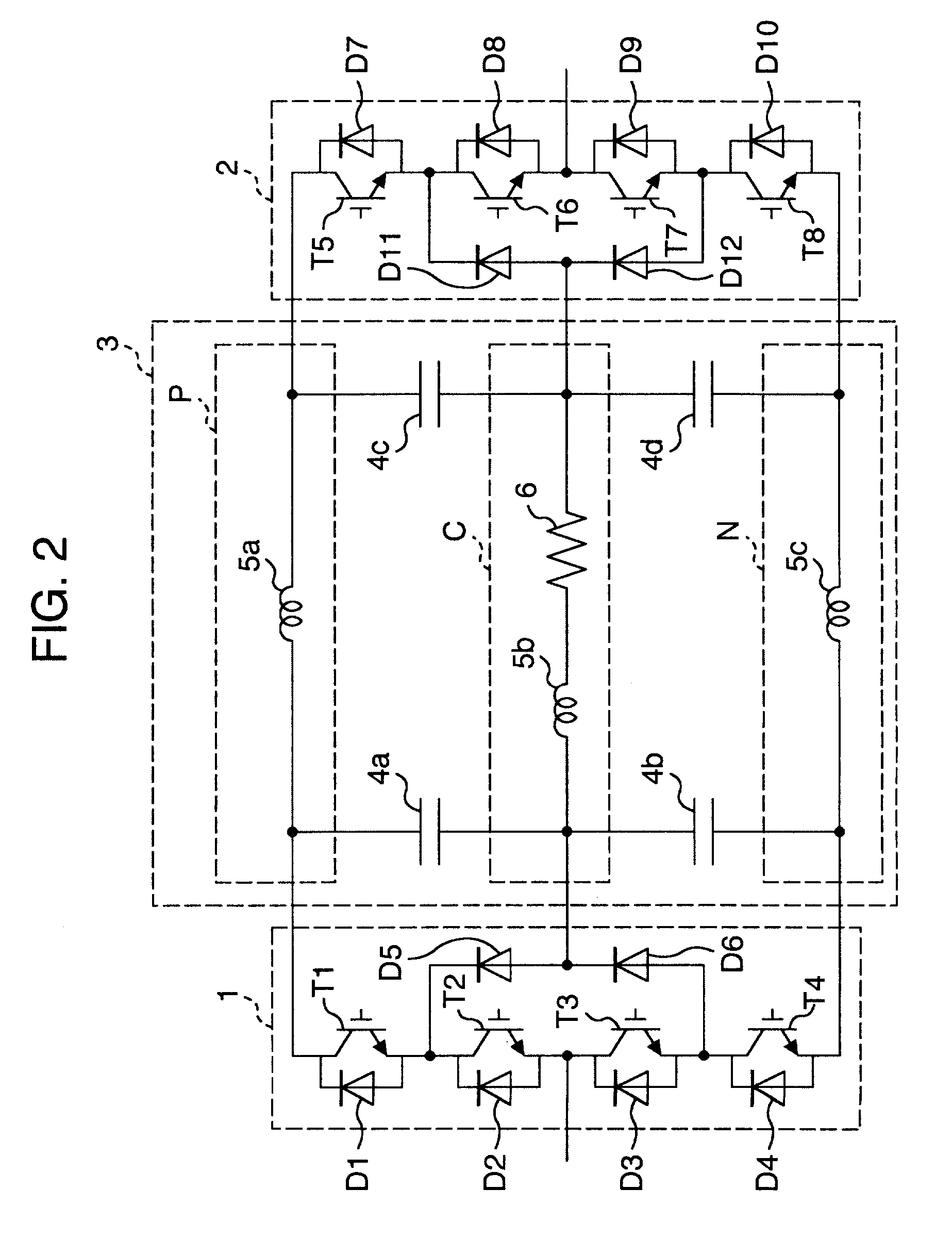
FIG. 2 shows a configuration of a three level inverter apparatus according to the present invention. This inverter apparatus comprises a three level converter 1 for converting an AC voltage from a power source to a DC voltage, a three level inverter 2 for converting the DC voltage to an AC voltage, and a DC link portion 3 for interconnecting these converter and inverter.

The three level converter 1 has diodes D1 through D4 connected in series between later-described plus-potential bus and minus-potential bus, diodes D5 and D6 connected in series between the interconnection point of the diodes D1 and D2 and that of the diodes D3 and D4, and bypass transistors T1 through T4 provided across the diodes D1 through D4 respectively. The interconnection point of the diodes D2 and D3 is connected to an AC input.

The three level inverter 2 has diodes D7 through D10 connected in series between the plus-potential and minus-potential buses, diodes D11 and D12 connected in series between an interco...

second embodiment

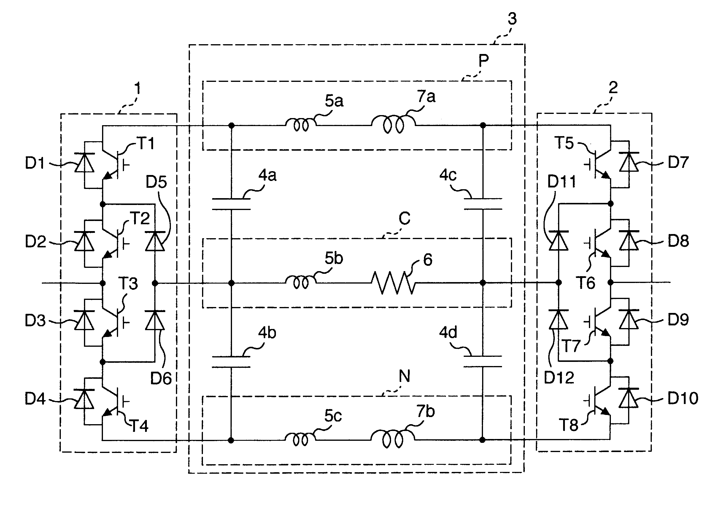
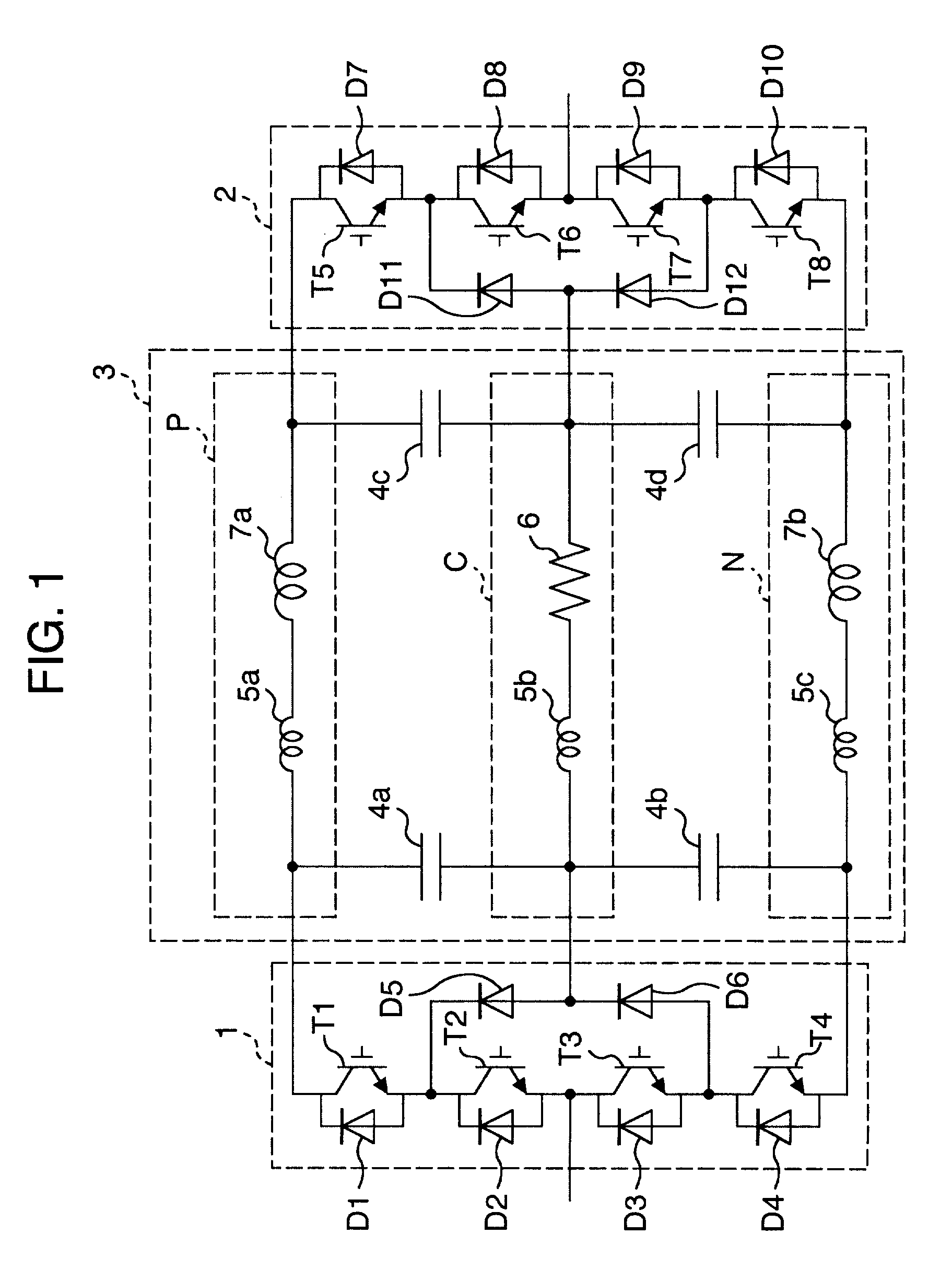
The following will describe the three level inverter apparatus according to the present invention with reference to FIG. 1. The like elements are given the like reference numerals in FIGS. 1 and 2. The apparatus according to this embodiment is different from that of FIG. 2 in that the plus-potential bus P and the minus-potential bus N have resonance-suppressing reactors 7a and 7b inserted therein respectively.

The following will describe about the two resonance paths X and Y in the DC link portion 4 of FIG. 1 with reference to FIG. 5. The resonance path X circulates along the smoothing capacitor 4a, the wiring inductance 5a, the resonance-suppressing reactor 7a, the smoothing capacitor 4c, the resonance-suppressing resistor 6, and the wiring inductance 5b in this order. The resonance path Y, on the other hand, circulates along the smoothing capacitor 4a, the wiring inductance 5a, the resonance-suppressing reactor 7a, the smoothing capacitors 4c and 4d, the resonance-suppressing react...


PUM


Abstract

A three level inverter apparatus for suppressing a resonance current flowing therethrough, to thus improve its conversion efficiency and operational stability. This inverter apparatus includes a converter 1 for converting AC power source power to DC power, an inverter for converting thus converted DC power to AC power, and a DC link for interconnecting these converter and inverter. This DC link has two first smoothing capacitors connected in series between a positive-polarity potential bus P and a negative-polarity potential bus N for storing DC power obtained by the converter 1 and two second smoothing capacitors connected in series between the positive-polarity potential bus P and the negative-polarity potential bus N for storing DC power to be supplied to the inverter. The positive-polarity and negative-polarity potential buses each have a resonance-suppressing reactor inserted therein and the intermediate-potential bus, a resonance-suppressing resistor inserted therein.

Description

1. Field of the InventionThe present invention relates to a power converter for generating variable-frequency power from electric power of AC power source.2. Description of the Related ArtAn inverter apparatus is widely used as a power converter for driving AC motors and, for large capacity use in particular, three level inverter apparatus is generally utilized.A typical inverter apparatus comprises a DC portion of a converter for converting AC power source power into DC power, a DC portion of an inverter for converting DC power into AC power, and a DC bus of a DC link portion which interconnects the former two portions. The DC portion of the converter and that of the inverter have their respective smoothing capacitors, in such a way that if a resonance frequency of a resonance circuit constituted by capacitance of these two smoothing capacitors and inductance of the DC bus approaches a switching frequency of the converter or the inverter, a large resonance current flows through the...

Claims


Application Information

Patent Timeline
IPC IPC(8): H02P27/04H02M7/527H02M5/458H02M7/505H02P27/14H02M5/00H02M7/12H02M7/48H02M7/483H02M7/5387H02M7/66
CPCH02M5/4585H02M7/527H02P27/14Y02P80/10H02M7/66
Inventor IKIMI, TAKASHI
Owner HITACHI LTD
Why Eureka
Try Eureka