Liquid crystal device and liquid crystal display apparatus having a chevron structure in monostable alignment

a liquid crystal display and chevron technology, applied in the direction of liquid crystal compositions, chemistry apparatus and processes, instruments, etc., can solve the problems of slow response speed of several ten milliseconds or above, difficulty in grading display in each pixel, and difficulty in improving the viewing angle characteristi

Inactive Publication Date: 2001-10-30
CANON KK
View PDF8 Cites 29 Cited by
  • Summary
  • Abstract
  • Description
  • Claims
  • Application Information

AI Technical Summary

Benefits of technology

In a similar manner as in above (measurement of &Hcirc ;) first and second extinction positions are obtained except that the applied voltage of the rectangular wave is changed to various values between the saturation voltage and zero volt

Problems solved by technology

In recent years, there has been proposed a liquid crystal device of In-Plain Switching mode utilizing an electric field applied in a longitudinal direction of the device, thus improving a viewing angle characteristic being problematic in TN-mode liquid crystal displays.
In any mode however, the resultant nematic liquid crystal display device has encountered a problem of a slow response speed of several ten milliseconds or above.
In the case of the above-mentioned device (cell) using an SSFLC, however, the device can basically effect only a display of two (display) levels, thus being difficult to effect a gradation display in each pixel.
However, these devices have not been put into practical use sufficiently.
When the above-mentioned chevron structure where the layer inclination angle .delta. in the cell thickness direction is a certain value as shown in FIGS. 5A, 5B, 6A and 6B is assumed, the liquid crystal molecules at the bending portion of the chevron structure are deviated (shifted) from the cone surface to result in an energistically disadvantageous (unstable) structure.
Particularly, in the case of switching of the SSFLC, the energy barrier becomes very large since the switching is accompanied with formation and extinction of domains (domain walls) as described above, thus consequently requiring a high driving voltage.
In this case, however, if the liquid crystal used has a large Ps value, the layer deformation due to the combination effect of the electric field and the Ps is liable to occur.

Method used


Image

  • Liquid crystal device and liquid crystal display apparatus having a chevron structure in monostable alignment
  • Liquid crystal device and liquid crystal display apparatus having a chevron structure in monostable alignment
  • Liquid crystal device and liquid crystal display apparatus having a chevron structure in monostable alignment

Examples


example 2

A liquid crystal cell was prepared in the following manner.

A pair of 1.1 mm-thick glass substrates each provided with a 700 .ANG.-thick stripe electrodes of ITO film as a transparent electrode were provided.

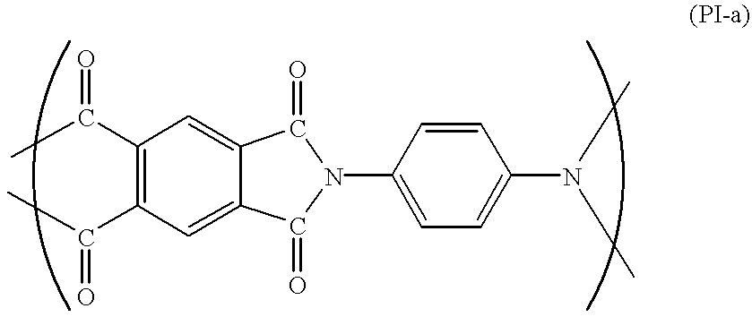
On each of the transparent electrodes, a polyimide precursor for forming a polyimide having a recurring unit (PI-b) shown below was applied by spin coating and pre-dried at 80.degree. C. for 5 min., followed by hot-baking at 200.degree. C. for 1 hour to obtain a 200 .ANG.-thick p olyimide film. (PI-b) ##STR8##

Each of the thus-obtained polyimide film was subjected to rubbing treatment (as a uniaxial aligning treatment) with a nylon cloth in the same manner as in Example 1.

Then, on one of the substrates, silica beads (average particle size =2.0 .mu.m) were dispersed and the pair of substrates were applied to each other so that the rubbing treating axes were in parallel with each other but oppositely directed (anti-parallel relationship), thus preparing a blank cell with a uniform c...

example 3

In this example, a liquid crystal device satisfying a relationship of .delta..ltoreq.&Hcirc ; by using a pressure application treatment in combination with a liquid crystal material having a relative large Ps.

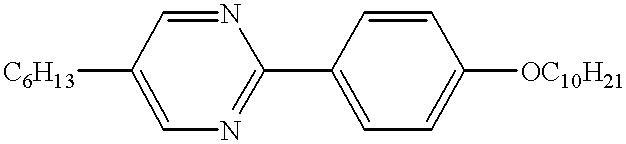
A liquid crystal composition LC-2 was prepared by mixing the following compounds in the indicated proportions.

The thus-prepared liquid crystal composition LC-2 showed the following phase transition series and physical properties. ##STR14##

Spontaneous polarization (Ps): 6.62 nC / cm.sup.2 (30.degree. C.)

Tilt angle &Hcirc ;: 22.1 degrees (30.degree. C.)

Helical pitch (SmC*): at least 20 .mu.m (30.degree. C.) (roughly calculated value due to a longer pitch)

The liquid crystal composition LC-2 was injected a blank cell (prepared in the same manner as in Example 1) in its isotropic liquid state and gradually cooled to a temperature providing chiral smectic C phase to prepare a liquid crystal device (Device C).

When the thus-prepared Device C was subjected to observation of its initial al...

example 4

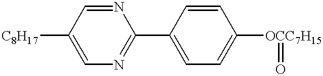
A liquid crystal composition LC-3 was prepared by mixing the following compounds in the indicated proportions.

The thus-prepared liquid crystal composition LC-3 showed the following phase transition series and physical properties ##STR22##

Spontaneous polarization (Ps): 0.96 nC / cm.sup.2 (30.degree. C.)

Tilt angle &Hcirc ;: 19.1 degrees (30.degree. C.)

Helical pitch (SmC*): at least 20 .mu.m (30.degree. C.)

The liquid crystal composition LC-3 was injected into a black cell (prepared in the same manner as in Example 1) in its isotropic liquid state and gradually cooled to a temperature providing chiral smectic C phase to prepare a liquid crystal device (Device D).

When the thus-prepared Device D was subjected to observation of its initial alignment state at 30.degree. C. through a polarizing microscope, the initial alignment state was found to be bistable states comprising two domains in mixture.

The Device D was subjected to application of a rectangular wave (.+-.40 volts, 10 Hz) for 5 min....


PUM


Abstract

A liquid crystal device has a pair of oppositely disposed substrates and a liquid crystal having chiral smectic C phase disposed therebetween. The liquid crystal is placed in an alignment state in chiral smectic C phase with smectic molecular layers forming a chevron structure. Under no electric field application, the liquid crystal has an average molecular axis substantially in alignment with the uniaxial alignment axis and / or a bisector of a maximum angle formed between two extreme molecular axes established under electric field application, while under electric field application, the liquid crystal provides an effective tilt angle and a transmittance that continuously changes depending on an electric field applied thereto.

Description

FIELD OF THE INVENTION AND RELATED ARTThe present invention relates to a liquid crystal device for use in light-valves for flat-panel displays, projection displays, printers, etc., and a liquid crystal display apparatus including the liquid crystal device. The present invention also relates to an aligning method of a liquid crystal in the liquid crystal device and a process for producing the liquid crystal device.As a type of a nematic liquid crystal display device used heretofore, there has been known an active matrix-type, a liquid crystal device wherein each pixel is provided with an active element (e.g., a thin film transistor (TFT)).As a nematic liquid crystal material used for such an active matrix-type liquid crystal device using a TFT, there has been presently widely used a twisted nematic (TN) liquid crystal as disclosed by M. Schadt and W. Helfrich, "Applied Physics Letters", Vol. 18, No. 4 (Feb. 17, 1971), pp. 127-128.In recent years, there has been proposed a liquid crys...

Claims


Application Information

Patent Timeline
IPC IPC(8): C09K19/42C09K19/02C09K19/34G02F1/13G02F1/141G09G3/36G02F1/133G02F1/1337G02F1/137
CPCC09K19/0225C09K19/3458C09K19/42G02F1/1416
Inventor TOGANO, TAKESHITERADA, MASAHIROMORI, SHOSEIASAO, YASUFUMIMORIYAMA, TAKASHI
Owner CANON KK
Why Eureka
Try Eureka