Valve timing adjusting device

Inactive Publication Date: 2001-11-06
DENSO CORP
View PDF27 Cites 42 Cited by
  • Summary
  • Abstract
  • Description
  • Claims
  • Application Information

AI Technical Summary

Problems solved by technology

At the heaviest load of the engine, moreover, a large amount of air has to be introduced into the cylinder of the engine.
When it is impossible to control the intake/exhaust valve, however, there may occur a problem such as the misfire or the combustion instability of the engine.
As a result, the oil pressure may be decreased by the leakage and the drop of the viscosity especially at a high oil temperature, and the actuator may not operate.
When an actuator having the same hydraulic piston area as that of the intake side, however, the exhaust side may not be controlled to the fundamental position, and the residual gas in the cylinder of the engine may increase to cause the misfire or stop the engine.
However, the torsion spring is structurally required to construct a spring around the whole circumference of the cam shaft.
This enlarged structure raises problems that the valve timing adjusting device is so raised in its weight and manufacturing cost as to make it difficult to mount it on the engi

Method used


Image

  • Valve timing adjusting device
  • Valve timing adjusting device
  • Valve timing adjusting device

Examples


first embodiment

Preferred embodiments of the present invention will now be described with reference to the accompanying drawings. First Embodiment

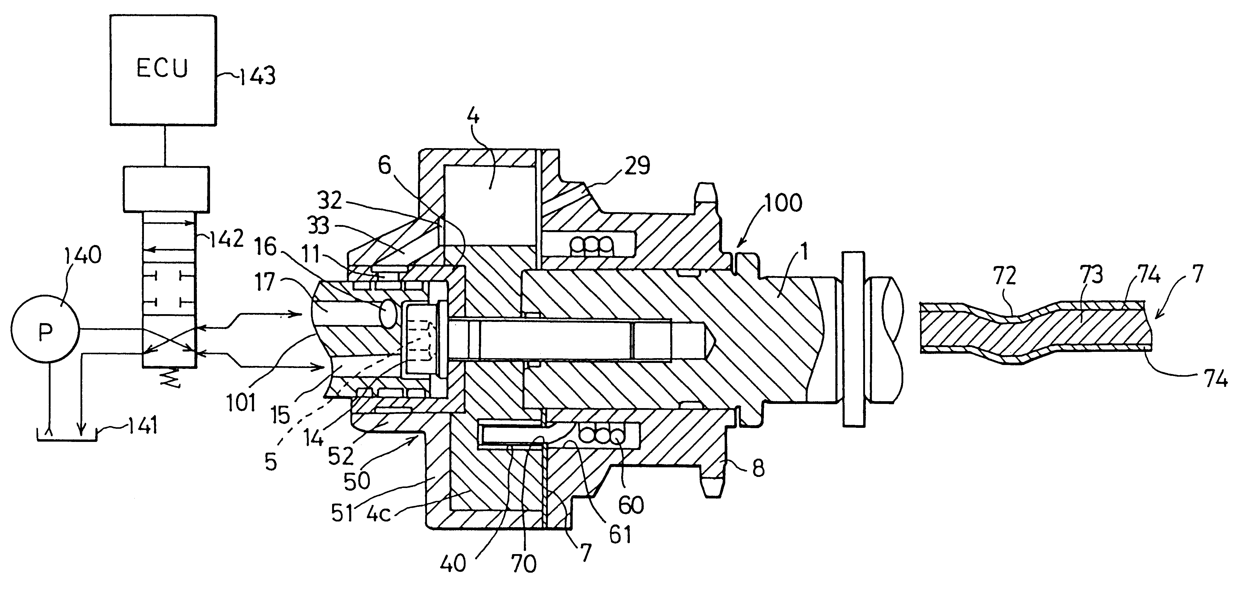
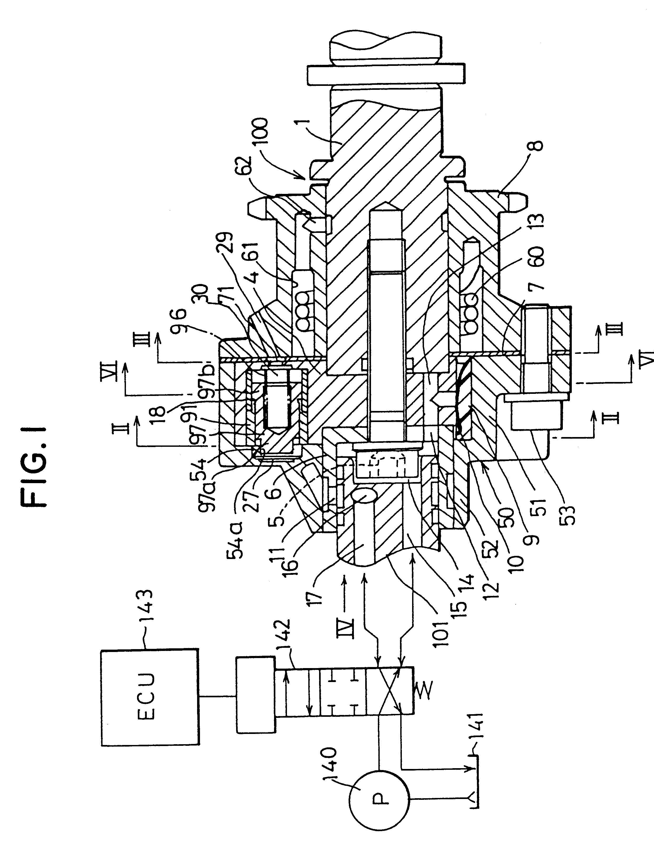
An engine valve timing adjusting device according to a first embodiment of the present invention is shown in FIGS. 1 to 10. This valve timing adjusting device 100 in the first embodiment is a hydraulic control type for controlling the valve timing of an exhaust valve.

A chain sprocket 8, as shown in FIG. 1, is coupled through the not-shown timing chain to a crankshaft acting as the drive shaft of the not-shown engine so that it is rotated in synchronism with the crankshaft by a driving force transmitted thereto. A front member 50 comprises a housing portion 51 and a bearing portion 52. The housing portion 51, the chain sprocket 8 and a later-described seal plate 7 are coupled by a bolt 53.

A cam shaft 1 acting as a driven shaft receives the driving force from the chain sprocket 8 to open / close the not-shown intake valve. The cam shaft 1 is supported by the ...

second embodiment

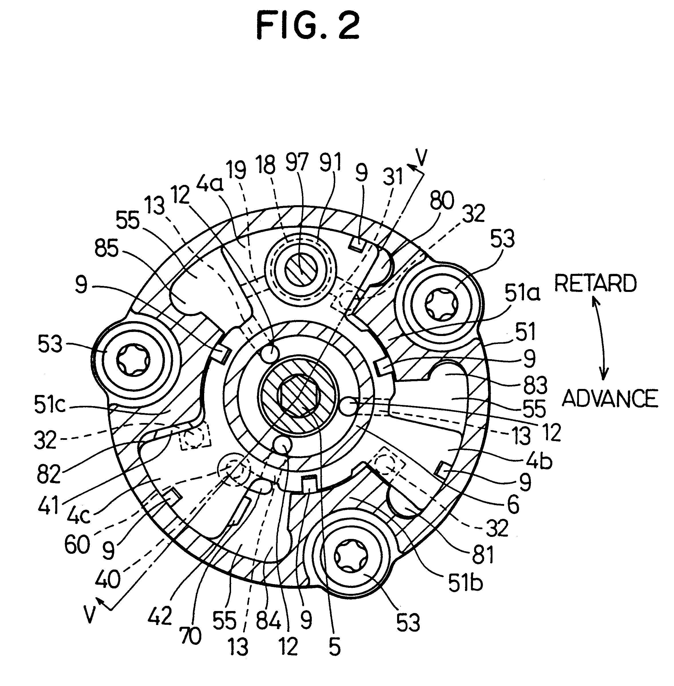
With reference to FIG. 11, a second embodiment of the present invention in which the fixing hole 40 of the first embodiment shown in FIG. 2 is formed in the vane 4a will now be described. The remaining structures are similar to those of the first embodiment. In this and the following embodiments, components which are substantially the same as those in previous embodiments are assigned the same reference numerals.

In the second embodiment, as shown in FIG. 11, there is formed in the vane 4a a fixing hole 44 for fixing one end portion of the torsion spring 60. As a result, this torsion spring 60 is assembled by fixing its other end portion on the chain sprocket without providing any special member for receiving the biasing force of the torsion spring 60 having a larger external diameter than the internal diameter of the vanes 4a, 4b and 4c.

Moreover, the fixing hole 44 is easily formed because the vane 4a to be provided with the stopper piston 97 as the abutting portion is made thicker ...

third embodiment

With reference to FIGS. 12 and 13, here will be described a third embodiment in which the other end portion of the torsion spring 60 of the first embodiment shown in FIGS. 1 and 3 is extended in the radial direction and in which the circumferential groove 61 is also extended in the radial direction. The remaining structures are similar to those of the first embodiment.

In the third embodiment, as shown in FIGS. 12 and 13, a torsion spring 160 functioning as first bias means is housed in a circumferential groove 161 formed as a housing space in a chain sprocket 108. The torsion spring 160 is fixed at its one end portion on the vane rotor 4 and at its other end portion on the chain sprocket 108. The other end portion of the torsion spring 160 is extended in the radial direction, and the circumferential groove 161 is so formed in the chain sprocket 108 that it is also extended in the radial direction.

The torsion spring 160 biases the vane rotor 4 in the direction of the vane rotor 4 to ...


PUM


Abstract

A seal plate partitions a sectorial space which houses a vane and a circumferential groove which houses a torsion spring, so that the sectorial space is formed to prevent the communication between an advance angle pressure chamber and a retard angle pressure chamber regardless of the space of the circumferential groove. As a result, by setting the inner diameter of the vane smaller than the outer diameter of the torsion spring, the outer diameter of the vane can be made relatively small without lowering the engine performance. Therefore, it is possible to reduce the actuator in size without lowering the engine performance, to reduce the weight of a valve timing adjusting device and to obtain a mounting space easily for mounting the valve timing adjusting device on the engine.

Description

1. Field of the InventionThe present invention relates to a valve timing adjusting device for changing the opening / closing timing (hereinafter referred to as the "valve timing") to open / close an intake valve and / or an exhaust valve of an internal combustion engine (hereinafter referred to as the "engine") in accordance with a drive condition.2. Related ArtThere has been known in the art a vane type valve timing adjusting device in which a cam shaft is driven by driving force transmitting mechanism such as a chain sprocket rotating in synchronism with the crankshaft of an engine so that the valve timing of at least one of the intake valve and the exhaust valve is controlled with a phase difference resulting from the relative rotations between the driving force transmitting mechanism and the cam shaft.In this vane type valve timing adjusting device, a vane rotating with the cam shaft is housed in a housing rotating with the driving force transmitting mechanism. By adjusting the relati...

Claims


Application Information

Patent Timeline
IPC IPC(8): F01L1/344
CPCF01L1/344F01L2001/34469F01L2001/34479F01L2001/34483F01L1/3442F01L1/022F01L1/024
Inventor USHIDA, MASAYASUSATO, OSAMUMORII, YASUSHIOONISHI, TOMOMASA
Owner DENSO CORP
Why Eureka
Try Eureka