Method and apparatus for controlling web tension by actively controlling velocity and acceleration of a dancer roll

a technology of active control and web tension, applied in the direction of dynamo-electric converter control, multiple dynamo-motor starters, instruments, etc., can solve the problem of direct control of the acceleration of the dancer roll, and provide an active

Inactive Publication Date: 2001-11-06
KIMBERLY-CLARK WORLDWIDE INC
View PDF51 Cites 159 Cited by
  • Summary
  • Abstract
  • Description
  • Claims
  • Application Information

AI Technical Summary

Benefits of technology

In some embodiments of the invention, the processing apparatus includes a sensor for sensing tension in the web after the dancer roll, the controller being adapted to use the sensed tension in computing the value and direction of the second variable force component, and for imparting the computed value and direction through the actuator apparatus to the dancer roll. The sensor can be effective to sense tension at least 1 time per second, and effective to recompute the value and direction of the second variable force component, thereby to adjust the value and direction of the computed second variable force component at least 1 time per second.
In other embodiments, the sensor can be effective to sense tension at least 500 times per second, the controller being effective to recompute the value and direction of the second variable force component, thereby to adjust the value and direction of the computed second variable force component at least 500 times per second, the actuator apparatus being effective to apply the recomputed second variable force component to the dancer roll at least 500 times per second according to the values and directions computed by the controller, thus to control the net translational acceleration.
In some embodiments, the sensor can be effective to sense tension at least 1000 times per second, the controller comprising a computer controller effective to recompute the value and direction of the second variable force component and thereby to adjust the value and direction of the computed second variable force component at least 1000 times per second, the actuator apparatus being effective to apply the recomputed second variable force component to the dancer roll at least 1000 times per second according to the values and directions computed by the computer controller, thus to control the net translational acceleration.
In some embodiments, the controller controls the actuating force imparted to the dancer roll, and thus acceleration of the dancer roll, including compensating for any inertia imbalance of the dancer roll not compensated for by the first static force component.

Problems solved by technology

A limitation of dancer rolls, as conventionally used, is that under more dynamic circumstances, the dancer's ability to maintain constant web tension depends upon the dancer system's mass, drag, and friction.
U.S. Pat. No. 5,659,229, however, controls the velocity of the dancer roll and does not directly control the acceleration of the dancer roll.
Thus, it is not known to provide an active dancer roll in a dynamic system wherein dynamic variations in operating parameters are used to calculate variable active response force components for applying active and variable acceleration to the dancer roll, and wherein appropriate gain constants are used to affect response time without allowing the system to become unstable.

Method used


Image

  • Method and apparatus for controlling web tension by actively controlling velocity and acceleration of a dancer roll
  • Method and apparatus for controlling web tension by actively controlling velocity and acceleration of a dancer roll
  • Method and apparatus for controlling web tension by actively controlling velocity and acceleration of a dancer roll

Examples


second embodiment

FIG. 8 shows control program flow diagram for the invention. In this embodiment, in step 1, the sensed variables are dancer translational velocity V.sub.p, web tension F.sub.c after dancer roll 24, and actuator apparatus or servo motor current I are measured.

In step 2, the web tension derivative dF.sub.ce / dt is computed. In one method the average force derivative is estimated using the equation:

dF.sub.ce / dt=[F.sub.c (present)-F.sub.c (previous)] / .DELTA.T

where

.DELTA.T=scan time,

F.sub.c =measured web tensions (most resent and previous scans), and

dF.sub.ce / dt=derivative of web tension.

Thus, the derivative of web tension is simply calculated from changes in web tension over the time interval or scan time of the system.

In step 3, estimated dancer acceleration A.sub.pe can be computed using translational velocity as described earlier. Likewise, motor current I can be utilized, in combination with the other sensed values of step 1, to compute dancer acceleration A.sub.pe.

In step 4, a ne...

third embodiment

FIG. 11 shows a control program flow diagram for a third embodiment of the invention. In this embodiment, in step 1, the variables of dancer translational velocity V.sub.p, web tension F.sub.c after dancer roll 24, and actuator apparatus or servo motor current I are measured.

In step 2, the web tension derivative dF.sub.ce / dt is computed. In one method the average force derivative is estimated using the equation set forth earlier in the second embodiment. Of course, the derivative of web tension can also be estimated using the observer set forth earlier in FIG. 10 of the second embodiment.

In step 3, estimated dancer acceleration A.sub.pe can be computed using translational velocity, as described earlier. In another method for step 3, actuator apparatus current I can be utilized, in combination with the other sensed values of step 1, to compute dancer translational acceleration A.sub.pe. Of course, in some embodiments, accelerometer 69 can be utilized to measure translational acceler...
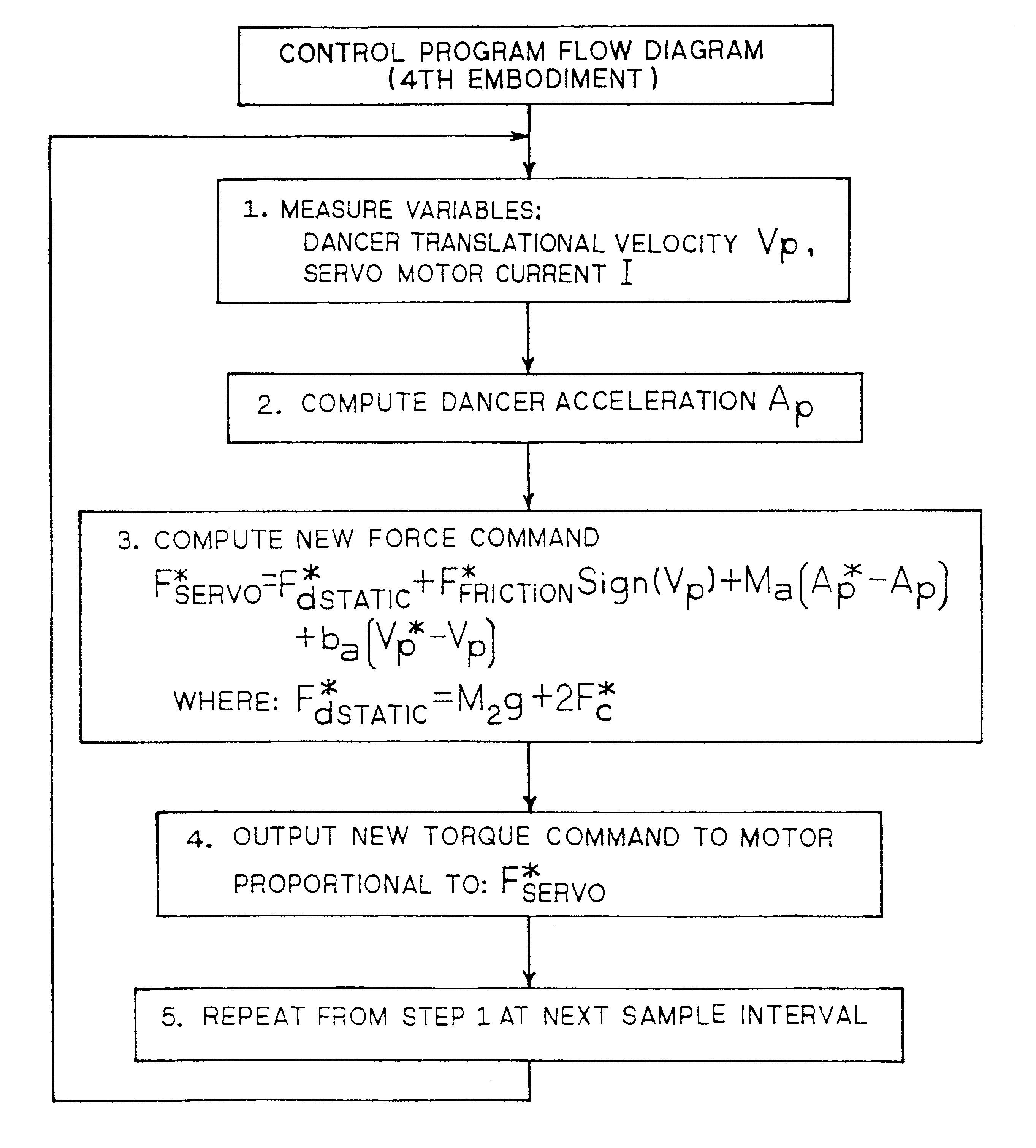
fourth embodiment

FIG. 14 shows a control flow program for a fourth embodiment of the invention. In this embodiment, in step 1, the only variables measured or sensed are dancer translational velocity V.sub.p and actuator apparatus or servo motor current I.

In step 2, dancer acceleration A.sub.pe can be computed or estimated by an observer using the equation described earlier:

A.sub.pe =[k.sub.1 (V.sub.p -V.sub.pe)+k.sub.te I-F*.sub.d static -F*.sub.friction Sign(V.sub.p)] / M.sub.2e

Thus estimated dancer acceleration is computed by an observer, as described earlier, using only dancer translational velocity V.sub.p and servo motor current I as measured inputs. All of the other elements are constants or values computed from translational velocity V.sub.p.

In step 3, a new force command F*.sub.servo is estimated using the equation shown therein. In step 4 a new output torque command proportional to F*.sub.servo is output to actuator apparatus 56 via zero order hold (ZOH). Actuator apparatus 56, in most embodi...


PUM


Abstract

This invention pertains to processing continuous webs such as paper, film, composites, and the like, in dynamic continuous processing operations. More particularly, it relates to controlling tension in such continuous webs during the processing operation. Tension is controlled in a dancer control system by connecting a corresponding dancer roll to an actuator apparatus or the like, sensing variables such as position, tension, velocity, and acceleration parameters related to the web and the dancer roll, and providing active force commands, in response to the sensed variables, to cause translational movement, generally including a target acceleration, in the dancer roll to control tension disturbances in the web. In some applications of the invention, the dancer control system is used to attenuate tension disturbances. In other applications of the invention, the dancer control system is used to create tension disturbances.

Description

Not ApplicableNot ApplicableThis invention relates to the processing of continuous webs such as paper, film, composites, or the like, in dynamic continuous processing operations. More particularly, the invention relates to controlling tension in such continuous webs during the processing operation.In the paper and plastic film industries, a dancer roll is widely used as a buffer between first and second sets of driving rolls, or first and second nips, which drive a continuous web. The dancer roll, which is positioned between the two sets of driving rolls, is also used to detect the difference in speed between the first and second sets of driving rolls.Typically, the basic purpose of a dancer roll is to maintain constant the tension on the continuous web which traverses the span between the first and second sets of driving rolls, including traversing the dancer roll.As the web traverses the span, passing over the dancer roll, the dancer roll moves up and down in a track, serving two ...

Claims


Application Information

Patent Timeline
Patent Type & Authority Patents(United States)
IPC IPC(8): B65H23/182B65H23/06B65H23/188B65H23/18B65H23/04
CPCB65H23/048B65H23/063B65H23/1825B65H23/1888B65H2511/112B65H2513/10B65H2513/21B65H2515/31B65H2515/32B65H2515/704B65H2557/22B65H2220/01B65H2220/02B65H2513/20B65H2515/70
Inventor RAJALA, GREGORY JOHNLORENZ, ROBERT DONALD
Owner KIMBERLY-CLARK WORLDWIDE INC
Why Eureka
Try Eureka