
Laser piercing method, laser processing nozzle, and laser cutting apparatus

a laser cutting and laser processing technology, applied in laser beam welding apparatus, manufacturing tools, welding/soldering/cutting articles, etc., can solve the problems of incomplete cutting, large increase in blowing away molten metal, and damage to the cutting nozzle 1 and the focusing lens,

Inactive Publication Date: 2001-11-13
NISSAN TANAKA
View PDF18 Cites 51 Cited by
  • Summary
  • Abstract
  • Description
  • Claims
  • Application Information

AI Technical Summary

Problems solved by technology

a. the piercing hole 5 diameter increases
b. the blowing away the molten metal greatly increases,
c. due to b, the cutting nozzle 1 and the focusing lens are sometimes damaged,
d. the sputter adhering to the cut work 3 increases, and
e. due to d, incomplete cutting is produced when the intended cutting commences.
However, because the problem of the adhesion of sputter to the lens and nozzle, no basic solution has been found for this problem.
Furthermore, attempts have been made to prevent the blowing away of molten metal and adhering of sputter by controlling the laser beam output during the piercing operation, but the piercing speed follows the control speed, and there are limits to increasing the speed.
Because of the above described situation, it is unavoidable that the piercing operation take a long time for a thick plate in particular.
Furthermore, it is difficult to obtain the intended shape of the piercing hole.
However, in the piercing operation for a thick plate, because the removal of molten metal from the piercing hole during formation is even more difficult, there are many cases in which the diameter of the piercing hole may become extremely large and the shape of the cross section become distorted, and due to the adhering of dross, the inner surface becomes extremely irregular.
In addition, there is an increase in self burning (sudden local burning of the cut work 3, etc.) at the commencement of the cutting, and the cut becomes unstable.
However, as the piercing time becomes long, the amount of heat input into the cut work becomes large during the piercing operation, the cut work becomes heated to a high temperature, and thereby when switching from piercing to cutting, there is excessive melting, and again an the probability of producing an incomplete cut becomes high.
In this manner, in the piercing operation for a thick plate, because it is difficult to obtain the intended shape of the piercing hole and because the cut work is heated to a high temperature due to the long piercing time thereby making excessive melting easily produced, the problems arise that incomplete cutting is easily produced, the cut at the commencement of cutting is unstable, and safely obtaining a high quality cut is not possible.
The cause is that as the piercing hole gradually increases in depth as the piercing operation progresses, it is increasingly difficult for the molten metal inside the piercing hole being formed to be removed to the outside of the cut work.
In this manner, if the removal of molten metal produced during the piercing operation is not smoothly removed, there may be an great increase in melting because the piercing operation time becomes lengthened, and in addition to this becoming a vicious cycle, influences the cutting operation which follows the piercing operation.
However, in the formation of a piercing hole in a thick plate, such as one having a thickness exceeding 12 mm, the blow gas discharged from the blow nozzle on the side of the nozzle enters the hole with difficulty, and it is difficult for the blow gas to reach the inside of the piercing hole during formation in the cut work.
Thus, the effect of preventing the excessive melting by the lowering of the oxygen concentration due to the blow gas with a low oxygen concentration by the cannot be sufficiently obtained.
Furthermore, in the blow gas discharged from one side of the cutting nozzle, it is difficult to make the lowering of the oxygen concentration inside the piercing hole uniform, and the uneven distribution of the oxygen concentration in the piercing hole cannot be avoided, and the effect of lowering the oxygen concentration cannot be sufficiently obtained.
In the technology disclosed in prior applications, if the piercing operation is carried out on a thin plate with a thickness of a few millimeters, the effect obtained from lowering the oxygen concentration by a blow gas can be obtained without a problem, but in forming a piercing hole in a thick plate exceeding 12 mm in thickness, there is the problem that the effects of preventing excessive melting and removal of molten metal, etc., by lowering the oxygen concentration is negligible.

Method used


Image

  • Laser piercing method, laser processing nozzle, and laser cutting apparatus
  • Laser piercing method, laser processing nozzle, and laser cutting apparatus
  • Laser piercing method, laser processing nozzle, and laser cutting apparatus

Examples


Embodiment Construction

Below, an embodiment of the present invention referring to the drawings.

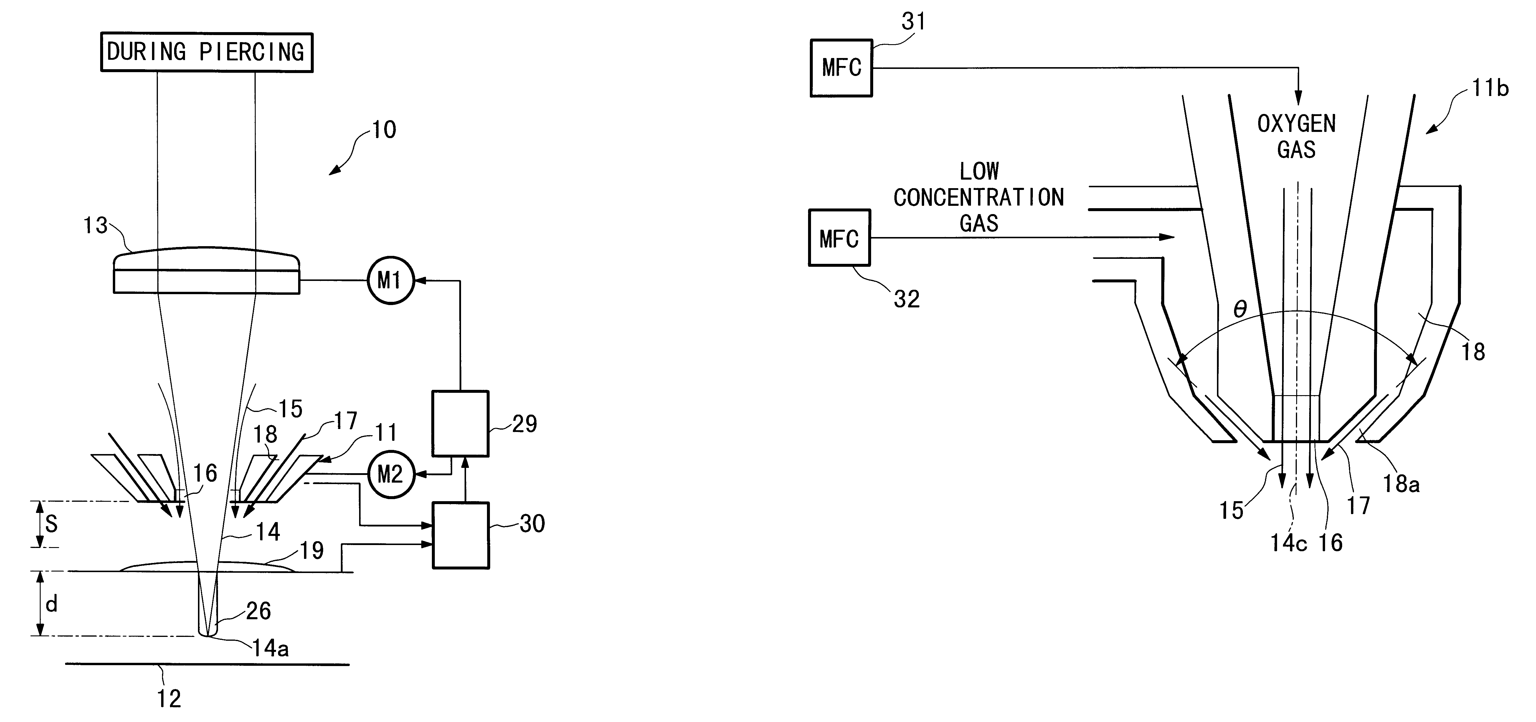
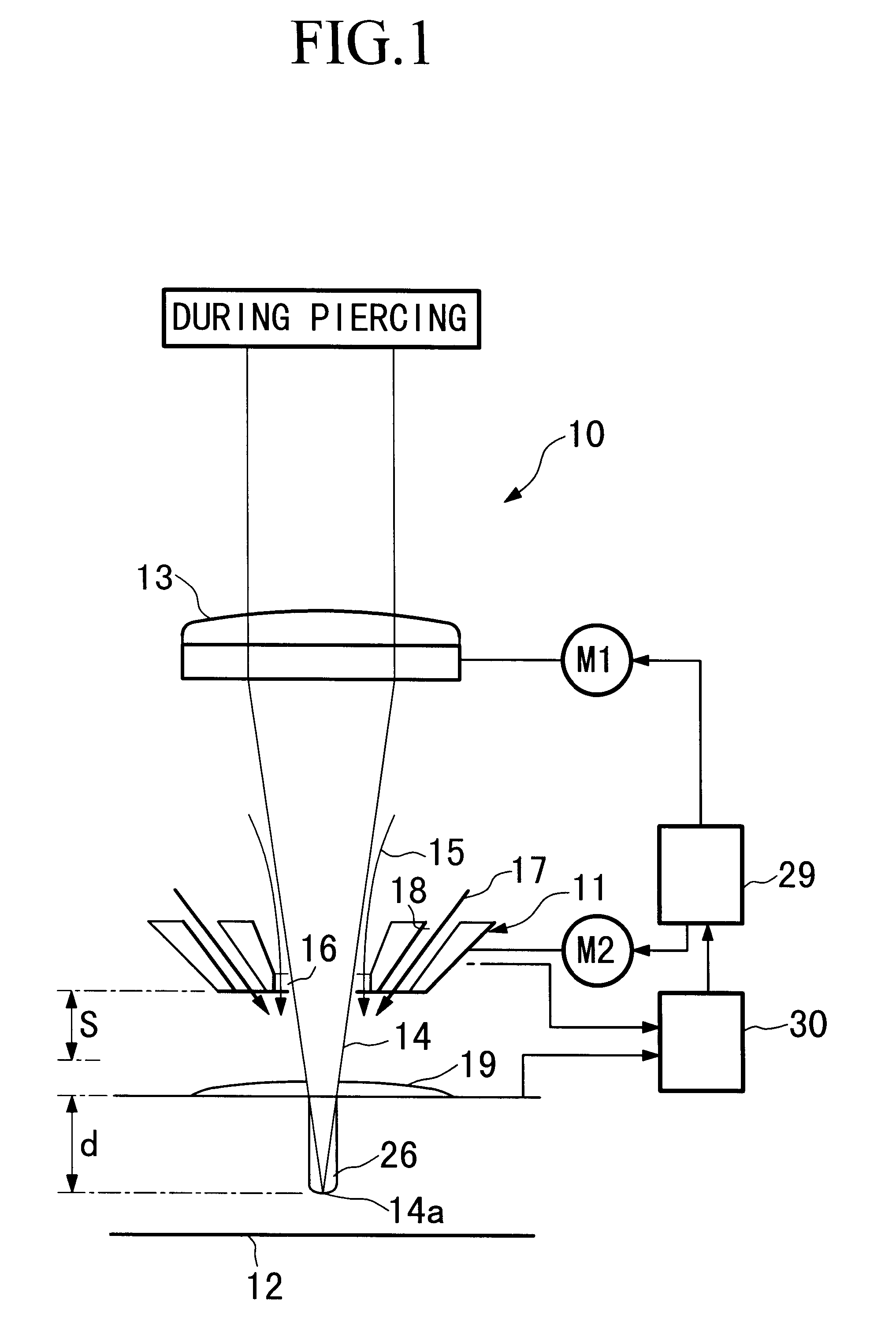
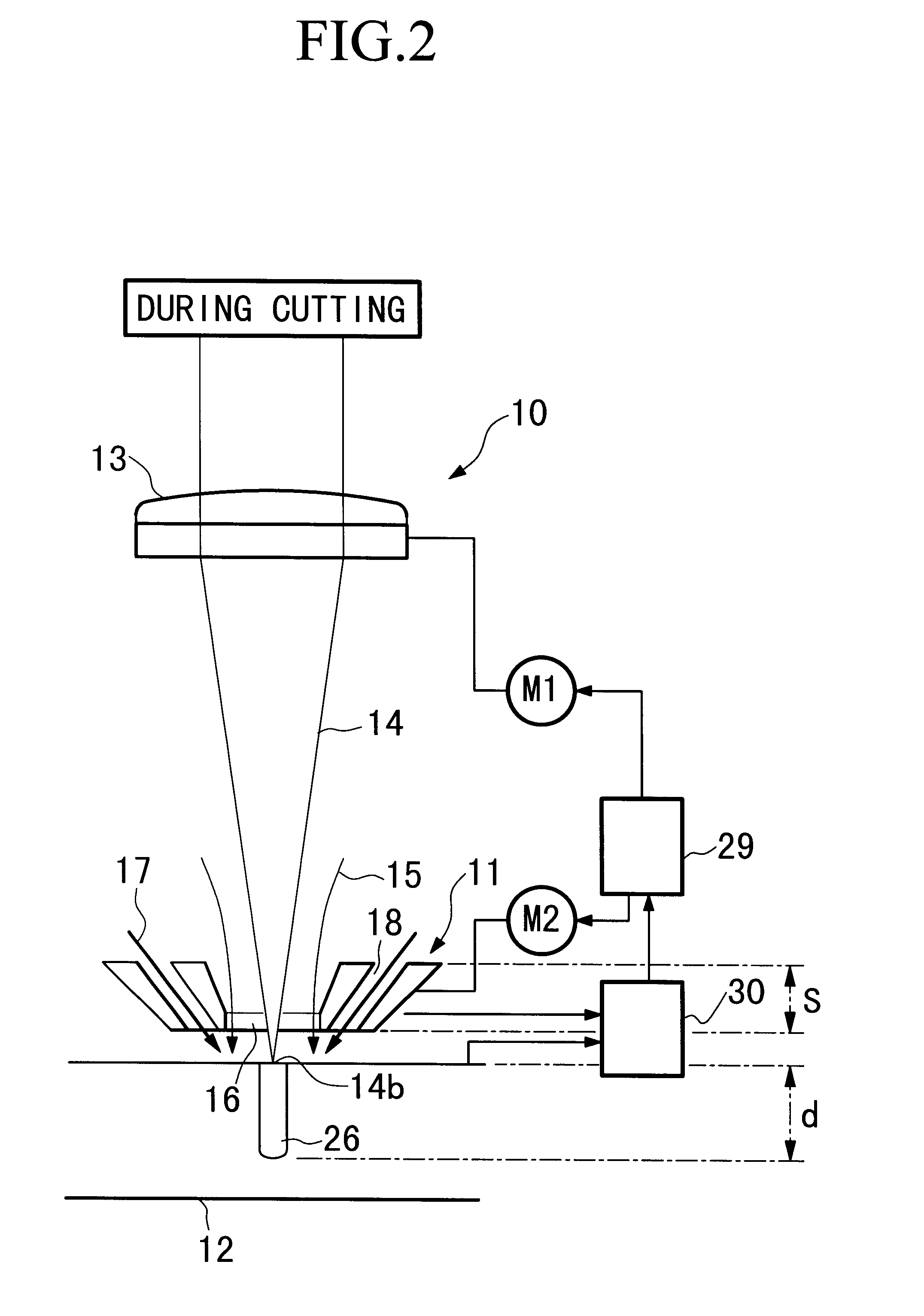
FIG. 1 and FIG. 2 are frontal views showing the vicinity of the processing head 10 of the laser cutting apparatus; FIG. 1 is during piercing, and FIG. 2 is during cutting.

In FIG. 1, in the laser piercing operation using this laser cutting apparatus is carried out by raising and lowering the laser processing nozzle 11 (hereinafter, abbreviated as "nozzle") by activating the nozzle activation mechanism M2, and positioning it at an appropriate position approaching the cut work 12 horizontally positioned below, and at the same time, by raining and lowering the lens 13 by activating the lens activation mechanism M1, positioning it where the laser beam applied to this cut work converges sop as to join the focal point of the cut work 12.

FIG. 3 is a cross-section showing a nozzle 11a which is an example of the nozzle 11.

In FIG. 3, the nozzle 11a provides an inner gas nozzle 16 through which the laser beam 14 (not shown ...


PUM

PropertyMeasurementUnit
thicknessaaaaaaaaaa
thicknessaaaaaaaaaa
thicknessaaaaaaaaaa

Abstract

In a piercing operation prior to the laser cutting of steel, etc., the development of a technology in which a piercing hole of the intended shape is obtained in a short time, even for a thick cut work. An oxygen gas coaxial to the laser beam applied towards the cut work and a low concentration gas with a low oxygen concentration and major components comprising nitrogen gas, air, or a mixture thereof discharged from an outer gas nozzle disposed so as to surround the outer side of the flow of this oxygen gas is supplied and disposed towards said cut work, and can realize shortening of the time, etc., of the piercing operation time by applying a laser beam to the cut work. In addition, a laser processing nozzle provided with an inner gas nozzle which discharges oxygen gas and an outer gas nozzle which discharges low concentration gas, and a laser cutting apparatus provided with this nozzle is provided.

Description

1. Field of the InventionThe present invention relates to a laser piercing method, a laser processing nozzle, and a laser cutting apparatus applied in the laser cutting of a cut work, such as a steel plate.2. Description of the Related ArtIn cutting, for example, a thick steel plate (a steal plate with a thickness of 6 mm or greater) by laser, usually the intended cutting operation commences after executing a piercing operation.Generally, a piercing operation, as shown in FIG. 13, consists in applying a laser beam 2 from a cutting nozzle 1 to the cut work 3, such as a steel plate, heating the cut work 3, and at the same time, by supplying an assist gas 4 which is coaxial to the laser beam 2, forming the piercing hole 5 by removing the molten metal 6 form the heated part of the cut work 3 by the kinetic energy of the assist gas 4. When implementing the piercing operation, part of the molten metal 6 accumulates around the piercing hole 5, and one part is scattered to places separated ...

Claims


Application Information

Patent Timeline
Patent Type & Authority Patents(United States)
IPC IPC(8): B23K26/38B23K26/00B23K26/14B23K26/12B23K26/04B23K26/046B23K26/142B23K26/16B23K26/382
CPCB23K26/04B23K26/123B23K26/125B23K26/1417B23K26/1435B23K26/1452B23K26/381B23K26/4005B23K2203/04B23K26/382B23K26/1438B23K26/146B23K26/40B23K2103/04B23K2103/50
Inventor NAGAHORI, MASAYUKINUMATA, SHINJIKAWAKITA, MASATO
Owner NISSAN TANAKA
Features
  • Generate Ideas
  • Intellectual Property
  • Life Sciences
  • Materials
  • Tech Scout
  • Unparalleled Data Quality
  • Higher Quality Content
  • 60% Fewer Hallucinations
Learn More