Control device for direct injection engine

a control device and direct injection technology, applied in the direction of electric control, ignition automatic control, machines/engines, etc., can solve the problems of not having the function of performing the quick light-off operation of the catalyst, not providing such effects, etc., to enhance the quick light-off effect, improve the properties of emissions, and maintain combustion stability

Inactive Publication Date: 2001-11-20
MAZDA MOTOR CORP
View PDF16 Cites 37 Cited by
  • Summary
  • Abstract
  • Description
  • Claims
  • Application Information

AI Technical Summary

Benefits of technology

The direct injection engine can improve the properties of emissions and enhance quick light-off effects while maintaining combustion stability by reducing the amounts of HC, NOx and other emissions and increasing the exhaust gas temperature when a catalyst is in its unheated state, and especially by adjusting the state of combustion in accordance with the engine temperature status when the catalyst is in its unheated state.

Problems solved by technology

Since HC is released in an earlier unheated state than that point, the device does not have the function of performing the catalyst quick light-off operation as a result of an increase in the exhaust gas temperature under such conditions.
Although it is desirable that the state of combustion be adjusted such that the combustion in the combustion chamber itself enhances HC and NOx reduction effects and quick light-off effects due to the increased exhaust gas temperature while maintaining combustion stability when the catalyst is in its unheated state, in which its temperature is lower than its activation temperature, the device of the aforementioned Patent Publication does not sufficiently provide such effects.
Although such changes in the fuel evaporation and atomization conditions could affect the combustion stability and quick light-off effects, for instance, due consideration has not been given to such points in the prior art.

Method used


Image

  • Control device for direct injection engine
  • Control device for direct injection engine
  • Control device for direct injection engine

Examples


Embodiment Construction

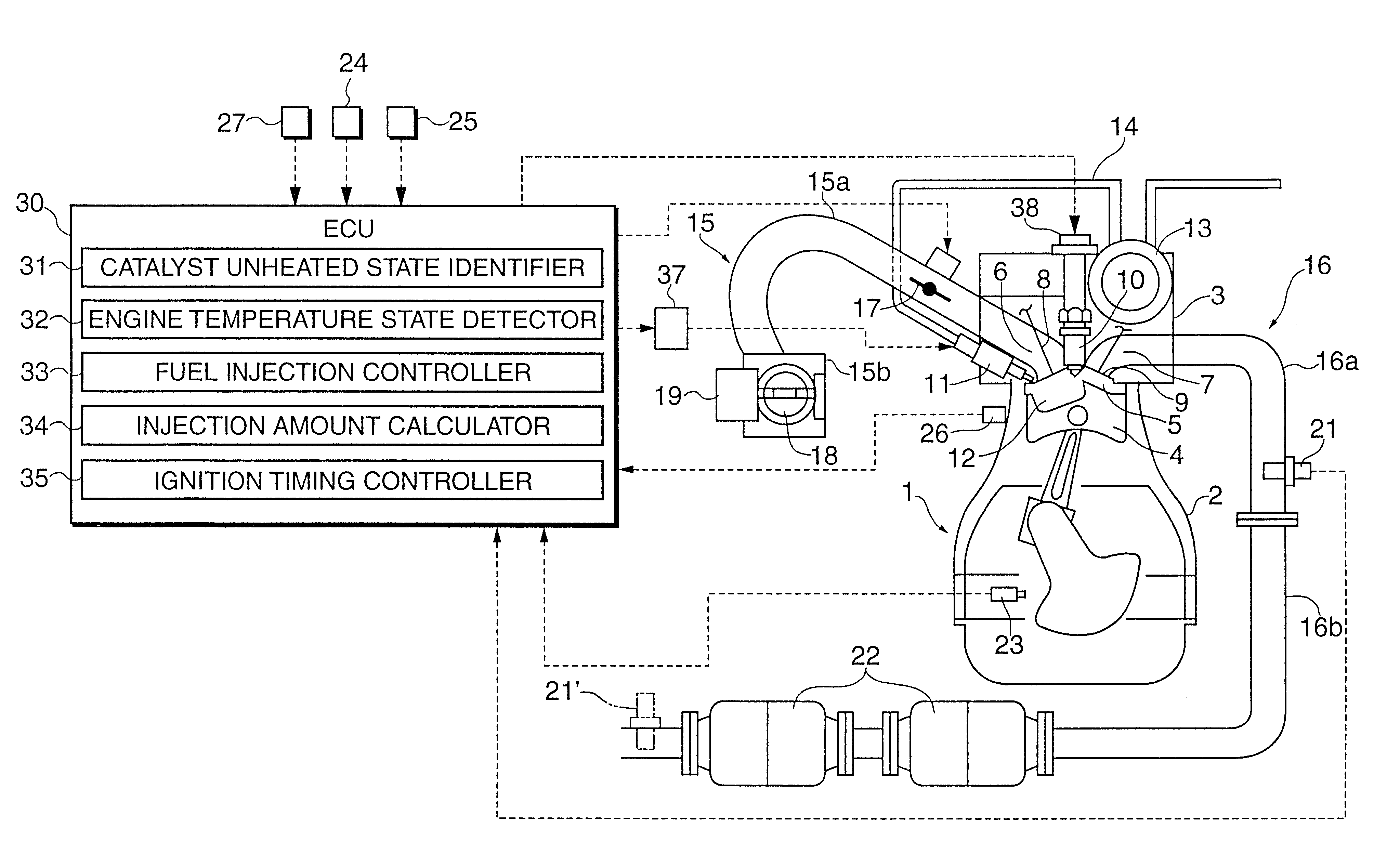
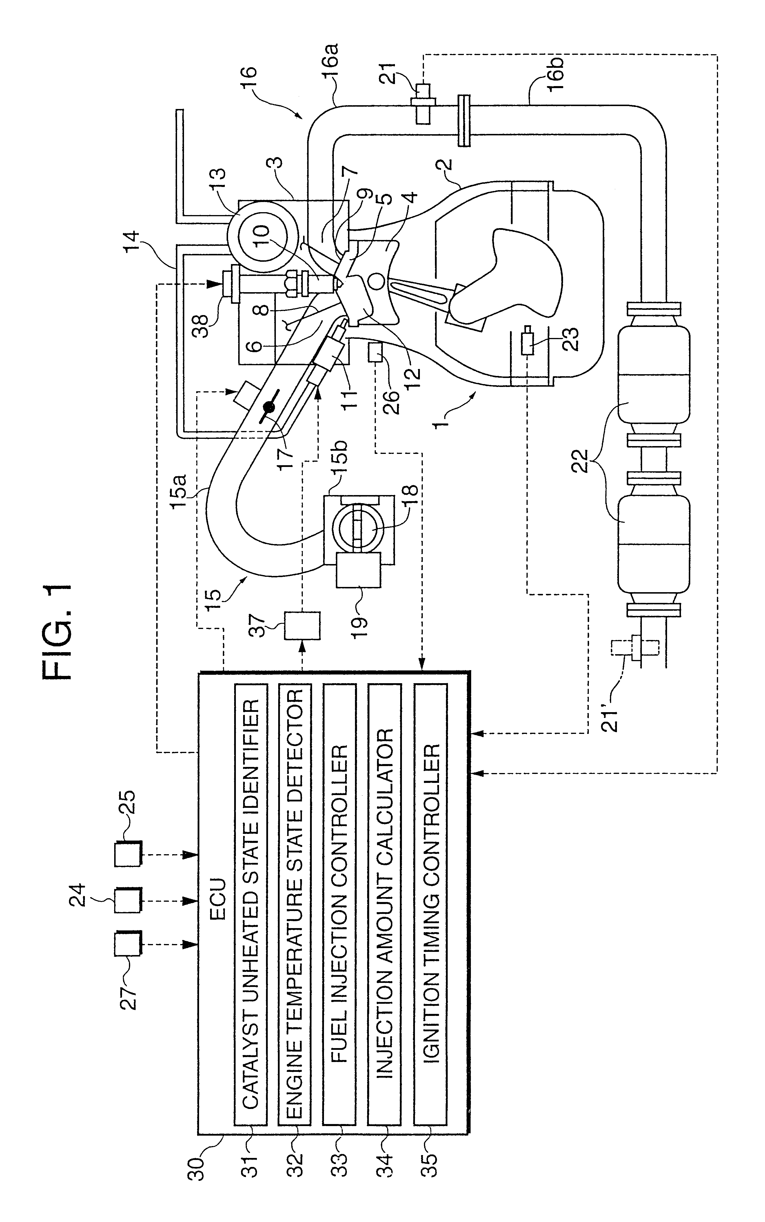
A direct injection engine and its control device according to a preferred embodiment of the invention is now described referring to the accompanying drawings.

FIG. 1 shows a practical example of the direct injection engine. In this Figure, designated by the numeral 1 is a main engine body which includes a cylinder block 2 and a cylinder head 3 in which a plurality of cylinders are formed. A piston 4 is fitted in each cylinder and a combustion chamber 5 is formed between the top surface of the piston 4 and the bottom surface of the cylinder head 3.

A recess having a particular shape is formed in the bottom surface of the cylinder head 3, the recess forming an upper interior surface of the combustion chamber 5. For example, the upper interior surface of the combustion chamber 5 is formed into a pent-roof shape as illustrated, and intake ports 6 and exhaust ports 7 opening into the combustion chamber 5 are formed in its upper interior surface. Although one each intake port 6 and exhaust ...


PUM


Abstract

A control device for a direct injection engine includes an identifier for judging whether a catalyst is in its unheated state in which its temperature is lower than its activation temperature, an engine temperature state detector for sensing the temperature state of the engine, and a fuel injection controller for controlling fuel injection from the injector. The fuel injection controller controls an injector in such a way that it makes at least two-step split injection including an earlier injection cycle performed during an intake stroke and a later injection cycle performed in a middle portion of a compression stroke or later when the catalyst is in its unheated state, and the later injection cycle is retarded when the catalyst is still in its unheated state but the engine temperature has become higher than a specified temperature compared to a case where the temperature of the engine is equal to or lower than the specified temperature.

Description

BACKGROUND OF THE INVENTION AND RELATED ART STATEMENTThis invention relates to a control device for a direct injection engine provided with an injector which injects fuel directly into a combustion chamber.A direct injection engine having an injector for injecting fuel directly into a combustion chamber is conventionally known. This engine is operated such that a condition in which a mixture is locally distributed around a spark plug is produced by injecting the fuel in a latter half of a compression stroke to perform so-called stratified charge combustion in a low-load state. This operation makes it possible to increase the air-fuel ratio to produce a leaner mixture while maintaining combustion stability and improve fuel economy.Exhaust gases from engines of motor vehicles, for instance, contain hydrocarbons (HC), carbon monoxide (CO) and nitrogen oxides (NOx), and there exists a demand today for reducing generation and release of these harmful constituents as much as possible to a...

Claims


Application Information

Patent Timeline
Patent Type & Authority Patents(United States)
IPC IPC(8): F02D41/06F02D41/14F02D41/30F02D41/02F02P5/15F02D41/40F02B75/12F02B75/00F01N3/20F02B31/00F02D41/04F02D41/34F02D45/00
CPCF02D41/024F02D41/068F02D41/1401F02D41/3023F02D41/402F02P5/1506F02B2075/125F02D2041/389F02F2001/241Y02T10/46Y02T10/44Y02T10/123Y02T10/26Y02T10/12Y02T10/40F02D41/30
Inventor NISHIMURA, HIROFUMIKUJI, YOUICHIKONO, SEIKOYAMASHITA, HIROYUKIARAKI, KEIJI
Owner MAZDA MOTOR CORP
Why Eureka
Try Eureka