Method and apparatus for determining a velocity

a velocity and velocity technology, applied in the direction of optical radiation measurement, instruments, spectrophotometry/monochromators, etc., can solve the problems of disturbance of coherence condition, inability to meet coherence condition, and inability to align and focus beams, so as to avoid signal dissipation or loss, reduce the requirement for optical quality of components, and avoid the effect of signal loss

Inactive Publication Date: 2001-11-20
DAIMLER AG
View PDF10 Cites 24 Cited by
  • Summary
  • Abstract
  • Description
  • Claims
  • Application Information

AI Technical Summary

Benefits of technology

The method and apparatus of the invention provide several advantages. For example, the detection method no longer requires that the coherence condition is satisfied. Thus, a local oscillator is also not necessary and the requirements for the optical quality of the components and the effort and expense for aligning and focusing the beam are substantially reduced. Furthermore, "speckles" do not result in a loss or dissipation of the signal that is used according to the invention as an intensity shift signal. The full backscattered or reflected laser signal can be used for processing substantially without regard to the magnitude of the wavelength shift, thereby avoiding signal dissipation or loss due to absorption or destructive interference, a difficulty that occurs with all conventional optical filter tec...

Problems solved by technology

The coherence condition might not be satisfied due to various reasons.
For example, it can be disturbed by depolarization or by polarization mismatch of both the emitted and the received signals.
Further, the coherence condition may not be satisfied due to wave-front disturbances resulting from a poor quality of the optical components, misalignment (wave-front tilt), or misfocussing (wave-front bending).
If the coherence condition is not satisfied, the usable signal recedes or diminishes rapidly or even disappears completely.
A further disadvantage of the conventional Doppler lidar method is that, the shorter the wavelength, the more difficult it is to satisfy the coherence condition.
This is disadvantageous because the backscattering in the atmosphere increases as the wavelength decreases.
Due to the difficulties of satisfying the coherence condition when using short wavelength signals, attempts have been made to replace the...

Method used


Image

  • Method and apparatus for determining a velocity
  • Method and apparatus for determining a velocity
  • Method and apparatus for determining a velocity

Examples


Embodiment Construction

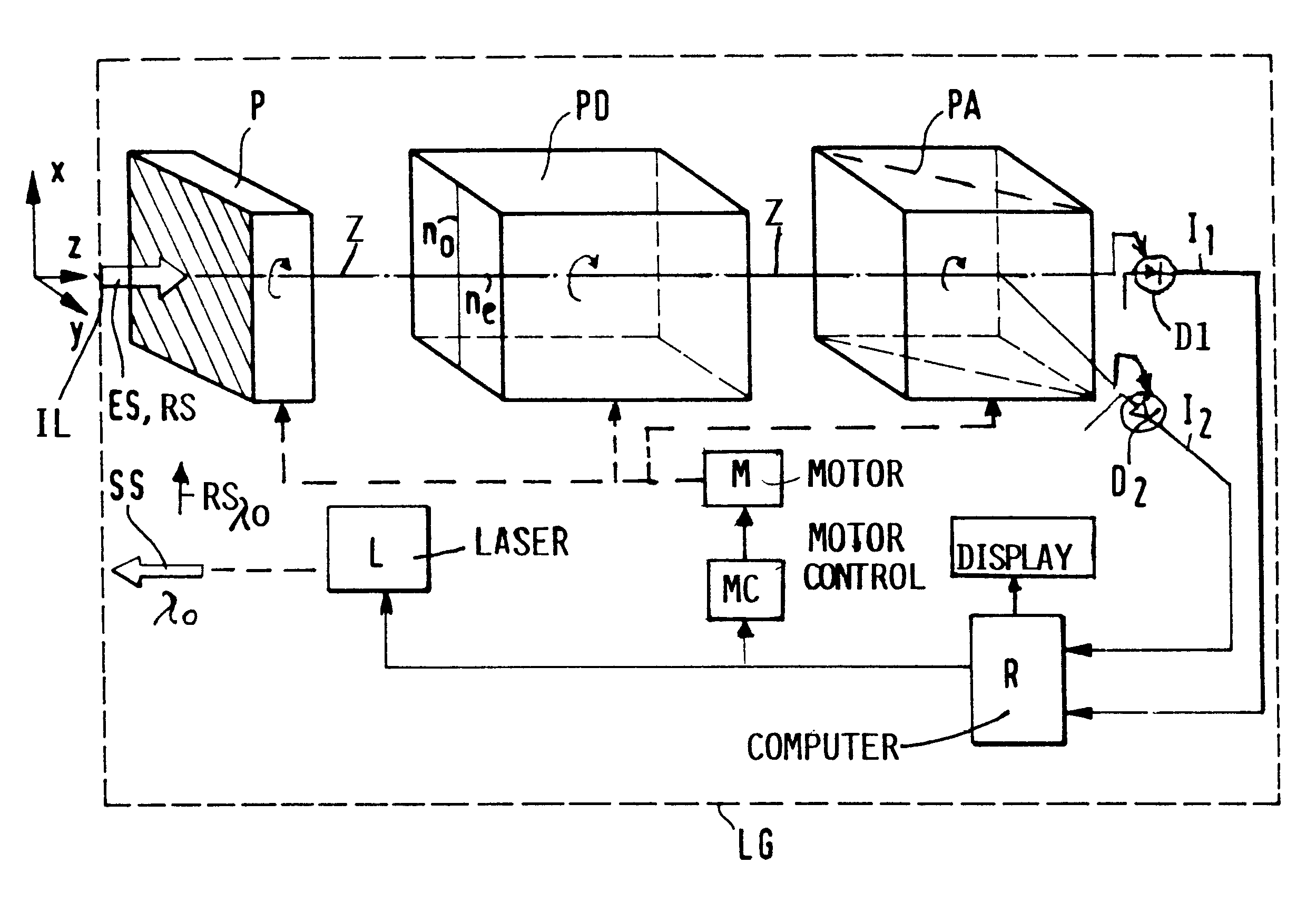
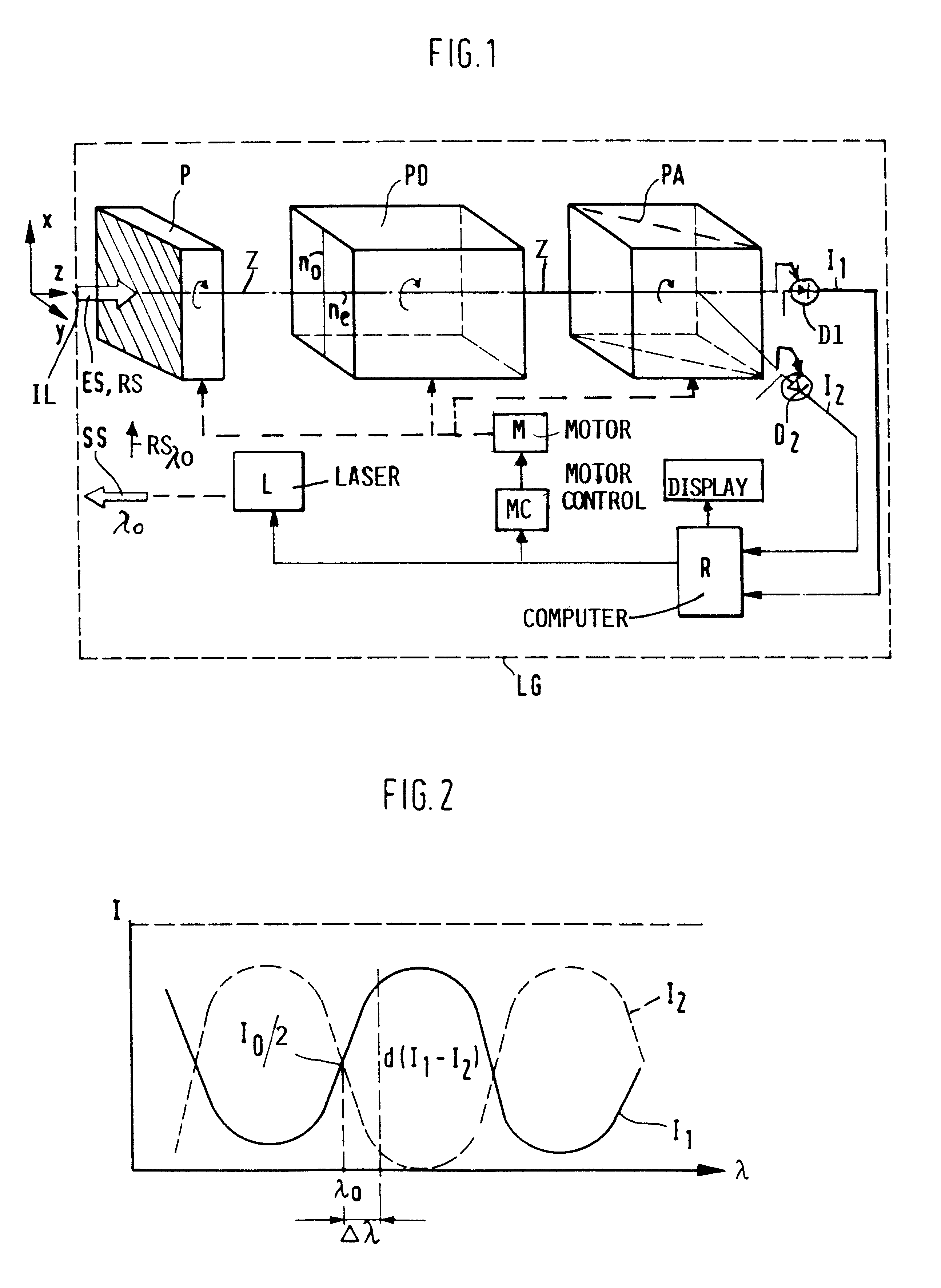
FIG. 1 shows schematically an example embodiment of a velocity measuring apparatus LG by determining the Doppler shift of a backscattered or received laser beam E5, based on a change in the polarization state of the backscattered beam and taking polarization intensity differences into account. A laser beam SS is emitted by a laser L, such as a lidar toward a target. The emitted beam SS has a wavelength .lambda..sub.0. When backscattered or reflected from moving objects, such as air molecules or aerosols, the wavelength of the backscattered beam ES is subject to a Doppler shift .+-..DELTA..lambda.. The backscattered beam ES, preferably, but not necessarily, first passes through a polarizer P in the direction of a Z-axis which is oriented in the direction of propagation of the backscattered beam ES. The beam or radiation ES, which enters a optical inlet IL of the apparatus LG, is linearly polarized by the polarizer P at an angle of 45.degree. to an X-axis and to a Y-axis of the X-Y-Z-...


PUM


Abstract

A velocity such as wind velocity is measured based on a Doppler shift of a backscattered or returned laser signal. The Doppler shift of the backscattered beam is determined from a change in the polarization state or intensity shift of the received or backscattered signal after it has passed through a polarization-dispersive element (PD) and through a polarization analyzer (PA). The electrical signals (I1 and I2) generated from two partial beams provided by the polarization analyzer (PA) represent an the intensity shift. The signals are processed in a computer and the resulting information is displayed, for example.

Description

This application is based on and claims the priority under 35 U.S.C. .sctn.119 of German Patent Application 199 13 049.3, filed on Mar. 23, 1999, the entire disclosure of which is incorporated herein by reference.INCORPORATION BY REFERENCEThe disclosure of U.S. Pat. No. 3,528,741 (Benson et al.), issued on Sep. 15, 1970; U.S. Pat. No. 4,988,190 (Miles), issued on Jan. 29, 1991; U.S. Pat. No. 5,029,999 (Kremer et al.), issued on Jul. 9, 1991; U.S. Pat. No. 5,088,815 (Garnier et al.), issued on Feb. 18, 1992; and U.S. Pat. No. 5,267,010 (Kremer et al.), issued on Nov. 30, 1993 is incorporated herein by referenceThe invention relates to a method and apparatus for determining a velocity from a Doppler frequency shift of a relocated or backscattered laser signal.BACKGROUND INFORMATIONThe Doppler lidar method is the classic method for determining velocities by measuring backscattered or reflected laser light. The wind lidar method, for example, detects a laser signal that is backscattered...

Claims


Application Information

Patent Timeline
IPC IPC(8): G01P5/26G01P5/00G01S17/00G01S17/58G01S7/499G01S7/48G01S7/481
CPCG01P5/26G01S7/4811G01S7/499G01S17/58
Inventor MANHART, SIGMUNDSCHMIDT, ELKE
Owner DAIMLER AG
Why Eureka
Try Eureka