Intake module
- Summary
- Abstract
- Description
- Claims
- Application Information
AI Technical Summary
Benefits of technology
Problems solved by technology
Method used
Image
Examples
Embodiment Construction
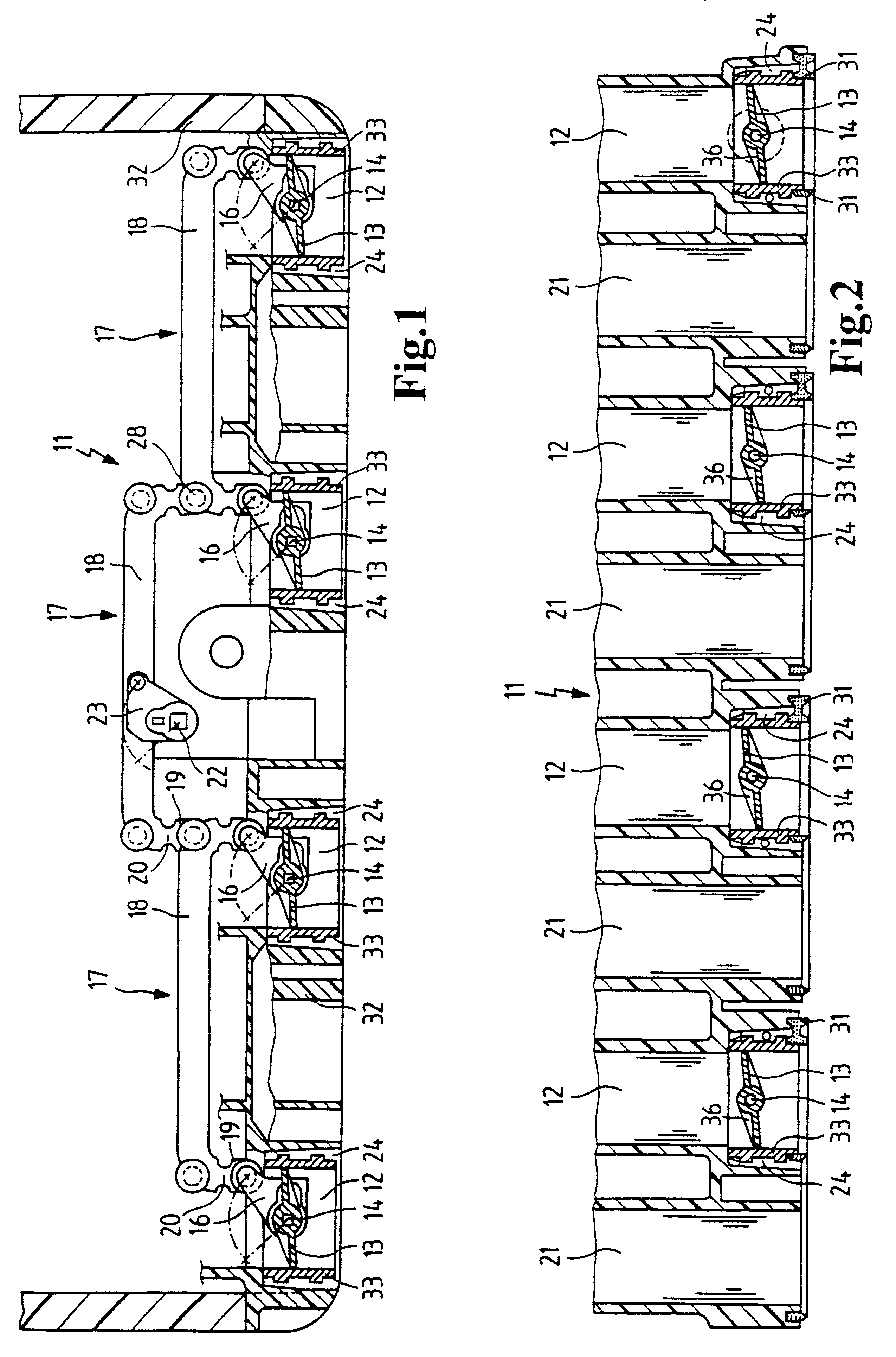
FIG. 1 shows an intake module 11 pursuant to the invention, in a longitudinal section, wherein only the connectable intake ducts 12 are shown. In these intake ducts 12 are the valves 13 represented in a side view, which are mounted for rotation on a shaft 14 passing through their center in the plane of the valve. In the position shown in FIG. 1, which is the same for all valves 13, they close the intake ducts completely.
At one end of the shaft 14 is an approximately triangular pivoting crank 16 through which the valves can be turned about the shaft. Within the scope of the invention it is also possible to provide the elastic part here. Thus either the pivoting cranks 16 can be elastic, or else preferably the shaft 14 can be equipped with a certain elasticity for a limited torsion, for example through the use of a suitable material or through a slimming of the cross section as the elastic part.
Initiation of the movement is made through main rods 17, one of which connects together the...
PUM
 Abstract
Description
Claims
Application Information
 - R&D
- Intellectual Property
- Life Sciences
- Materials
- Tech Scout
- Unparalleled Data Quality
- Higher Quality Content
- 60% Fewer Hallucinations
Browse by: Latest US Patents, China's latest patents, Technical Efficacy Thesaurus, Application Domain, Technology Topic, Popular Technical Reports.
© 2025 PatSnap. All rights reserved.Legal|Privacy policy|Modern Slavery Act Transparency Statement|Sitemap|About US| Contact US: help@patsnap.com


