
Method for operating a stove in a building, and a device for carrying out this method

a technology for operating stoves and buildings, which is applied in the direction of combustion processes, lighting and heating apparatuses, heating types, etc., can solve the problems of causing condensation, poor control of heat exchange air currents, and inability to remove disadvantages, so as to avoid stagnation pressure and achieve sufficient air change in the building

Inactive Publication Date: 2001-11-27
KALSNES HELGE
View PDF12 Cites 4 Cited by
  • Summary
  • Abstract
  • Description
  • Claims
  • Application Information

AI Technical Summary

Benefits of technology

The technical effect following use of combustion furnaces in buildings with an interior overpressure, made of preheated outdoor air, is that drifting of cold outdoor air through the ordinary leakage-points of the house, for example windows, door frames, and keyholes, are eliminated. The net positive effect of this is that the temperature of the air in the building generally becomes more uniform, and the danger of formation of moisture and rot damage at the ordinary leakage points is reduced.
Secondarily, there will always be an overpressure in the air supply to the furnace, compared to the pressure at the flue outlet, and in this way, the furnace is operated with increased oxygen supply, which in turn increases the combustion effect and utilization of the fire wood. It is also possible to reduce the spill of noxious gasses through the higher temperature in the smoke tube. Another positive effect of the invention is especially experienced when firing, since it gets a lot easier to set fire to, for example, fire wood in a wood-burning stove. One will therefore achieve a generally more uniform room temperature with lesser fuel consumption.
The preheated fresh air is advantageously led straight to the area by the furnace. The preheating of the air can take place in an arbitrary familiar way, for example by using a mantel around the smoke tube. Such a technical solution requires a small building volume, and consequently low costs for installation and maintenance.
In windy areas where there are high winds much of the year, it could be appropriate to place more outlet devices at different wall sections in order to avoid stagnation pressure from outdoor wind which would otherwise restrain removal of excess air from the interior of the building.

Problems solved by technology

There are several disadvantages concerning use of a combustion furnace in houses and similar buildings.
This heat exchange offers poor control of the air currents, both concerning whereform and whereto.
However this solution does not remove the disadvantages concerning the unequal temperature allocation in the building and the creation of condensation in cold and damp areas.
In addition to the combustion- and heating problems which hopefully will be improved, there is an unfortunate collection of gasses and evaporation in certain areas, in many houses or the similar with combustion furnaces.

Method used


Image

  • Method for operating a stove in a building, and a device for carrying out this method
  • Method for operating a stove in a building, and a device for carrying out this method

Examples


Embodiment Construction

The invention is illustrated in the drawings, wherein

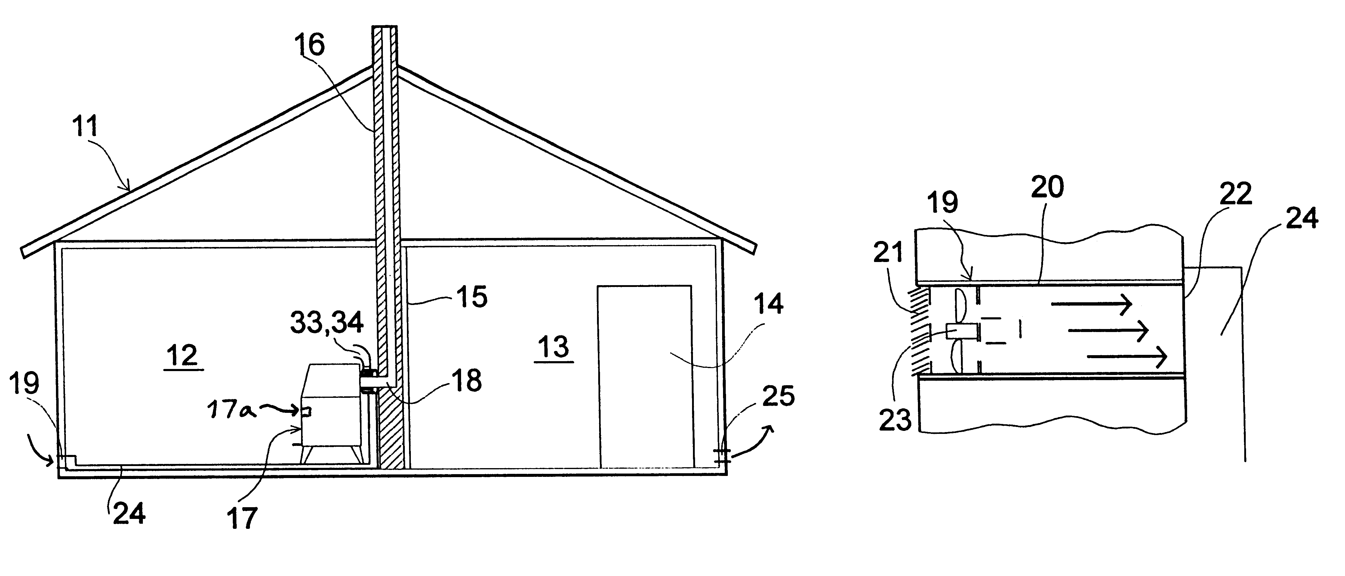
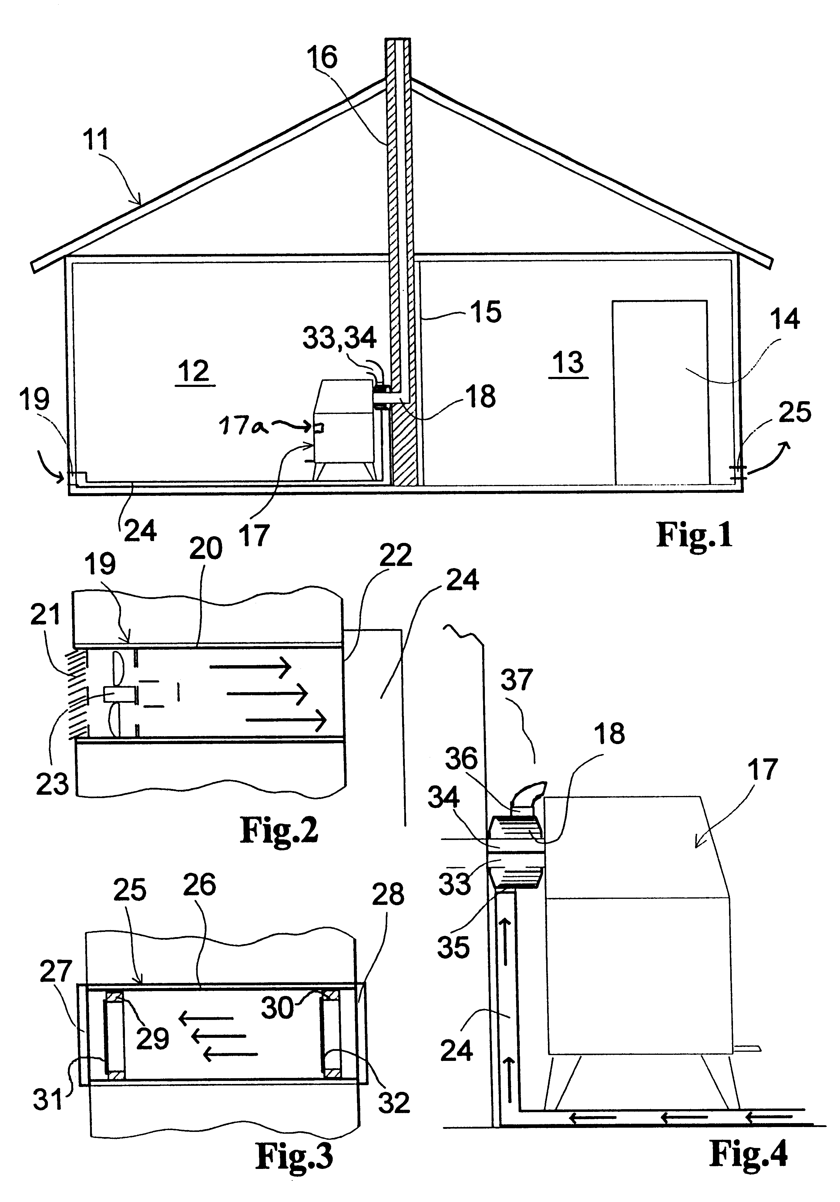
FIG. 1 shows a schematical section through a device according to the invention,

FIG. 2 shows a section through an inlet device,

FIG. 3 shows a section through an outlet device,

FIG. 4 shows a side section of an furnace for use in a device according to the invention.

FIG. 1 shows a building 11, e.g. house, which in this case is simplified to an inner room 12 and an outer room 13 with a front door 14. In the bulkhead 15 between the two rooms, is placed a smokepipe 16. In the bulkhead 15 there also exists a door opening, but this is not shown. Close to the smokepipe 16 is installed a wood-burning stove 17 with a smoketube 18 into the smokepipe. The wood-burning stove 17 could alternatively be a furnace or open fireplace, possible for burning fuels other than fire wood. The smoke tube may be led out of the room through a wall.

At the outer wall in the inner room 12 there is in an opening, placed within which is an inlet device 19 (FIG. 2) ...


PUM


Abstract

Method to operate a combustion device in a house or similar building, with fossil fuel furnaces, such as wood or oil furnaces. Outdoor air is supplied to a heat exchanger that is connected to the smoke tube of the furnace, in such an amount that an interior excess pressure is created, as excess air is led out of the interior of the building through one or more exhaust openings, especially exhaust devices, which are located at low places in the building at its outer side. This offers better combustion efficiency, better energy-utilization and a more uniform temperature in the building. A device for operating the method, comprises a fan (23) which takes in air from an inlet (19) near the outer walls of the building, through a tube (24) leading to the furnace, with a heat exchanger (33, 34) enclosing some of the smoke tube (18) of the furnace (17). The fan (23) is dimensioned and operated to create an overpressure in the building. There exists at least one overflow valve (25) placed in the lower parts of the building, near its outer wall, which opens upon a low inner pressure.

Description

There are several disadvantages concerning use of a combustion furnace in houses and similar buildings. In order to supply air for combustion, cold air are drawn in from various leaks in the building. Draughts and unequal temperature allocation will thus arise, with high temperatures around the furnace and cold spots at areas where the cold air is drawn in.From Norwegian patent publication 59825, blowing air around a furnace is known. Simultaneously, it is suggested to suck outdoor air into the room. This heat exchange offers poor control of the air currents, both concerning whereform and whereto. The furnace temperature is reduced as is the corresponding combustion efficiency.In U.S. Pat. No. 2,610,565 the inner negative pressure in rooms with combustion furnaces, is reduced by sucking in filtered outdoor air. In this way the suction of uncontrolled and unfiltered air gets moderated. However this solution does not remove the disadvantages concerning the unequal temperature allocati...

Claims


Application Information

Patent Timeline
IPC IPC(8): F23L5/02F23L15/00F24B7/00F24F11/00F23L5/00F23L17/00F23L17/04F24F7/08F24F7/10
CPCF23L5/02F23L15/00F24B7/005F24F11/0001F24F2011/0004Y02A40/928Y02E20/34
Inventor KALSNES, HELGE
Owner KALSNES HELGE
Learn More