Planar magnetron with moving magnet assembly

a technology of moving magnets and magnet arrays, applied in the direction of diaphragms, electrodes, ion implantation coatings, etc., can solve the problems of large size, complex drive mechanism of moving magnet arrays, and inability to produce elongated plasma race-tracks

Inactive Publication Date: 2001-11-27
BEKAERT ADVANCED COATINGS
View PDF11 Cites 72 Cited by
  • Summary
  • Abstract
  • Description
  • Claims
  • Application Information

AI Technical Summary

Problems solved by technology

As explained in U.S. Pat. No. 4,714,536, these known magnet and target assemblies do not provide a substrate with a satisfactorily uniform sputtered coat nor do they provide a satisfactorily uniform erosion of the target.
The kidney bean shape does not produce an elongated plasma race-track and is not suitable for rectangular targets.
The drive mechanism for moving the magnet array is complex and large in size and requires separate guides f

Method used


Image

  • Planar magnetron with moving magnet assembly
  • Planar magnetron with moving magnet assembly
  • Planar magnetron with moving magnet assembly

Examples


Embodiment Construction

The present invention will be described with respect to particular embodiments and with reference to certain drawings but the invention is not limited thereto buy only by the claims. The drawings described are only schematic and are non-limiting.

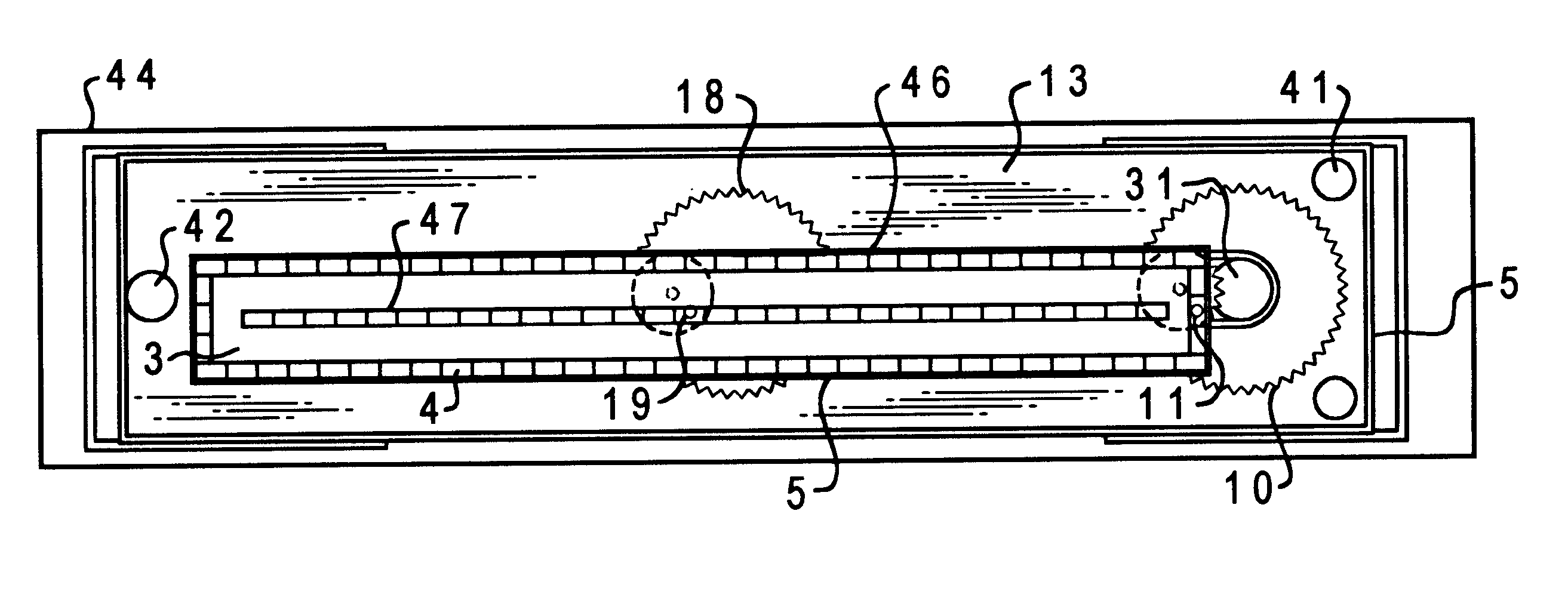
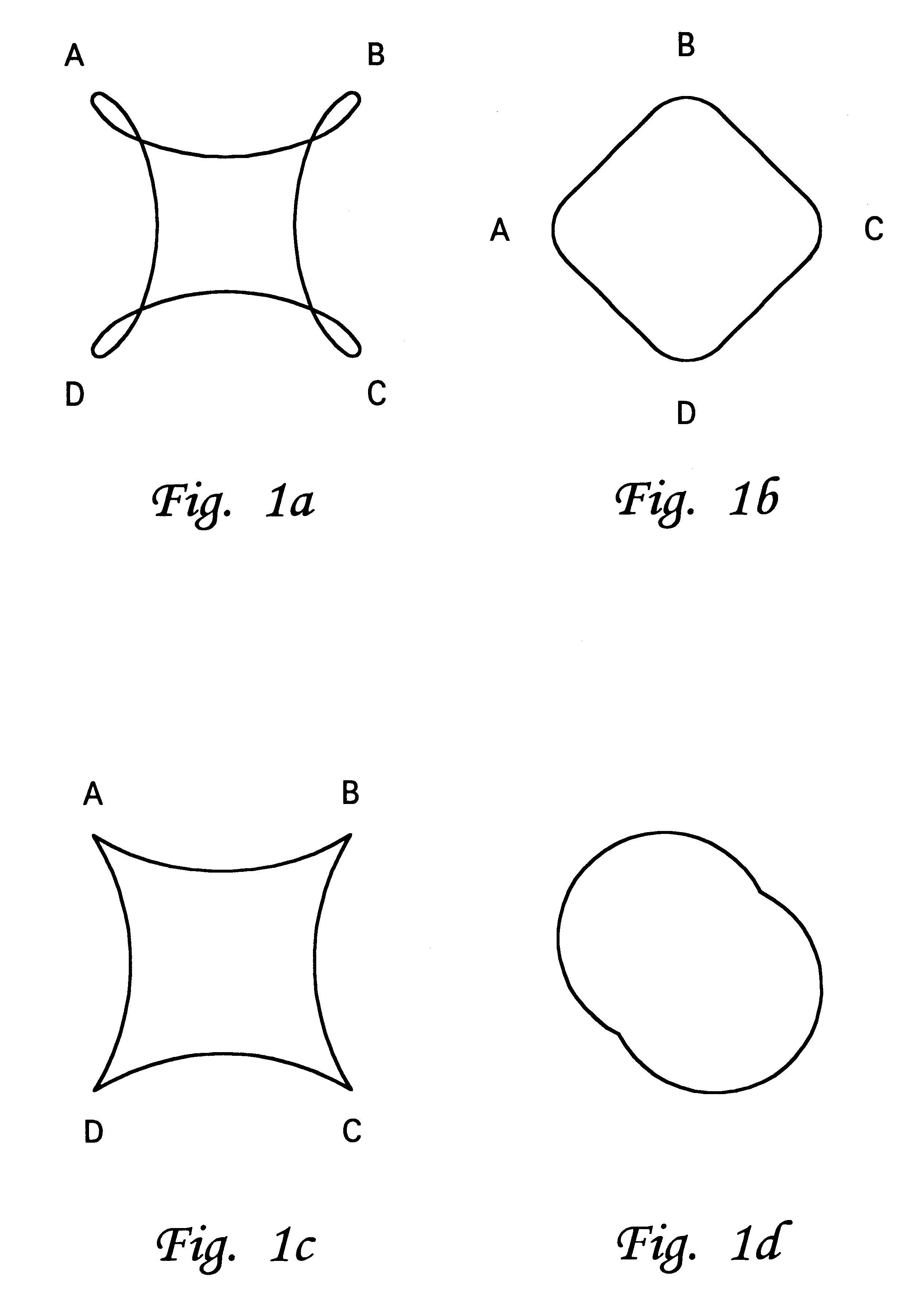
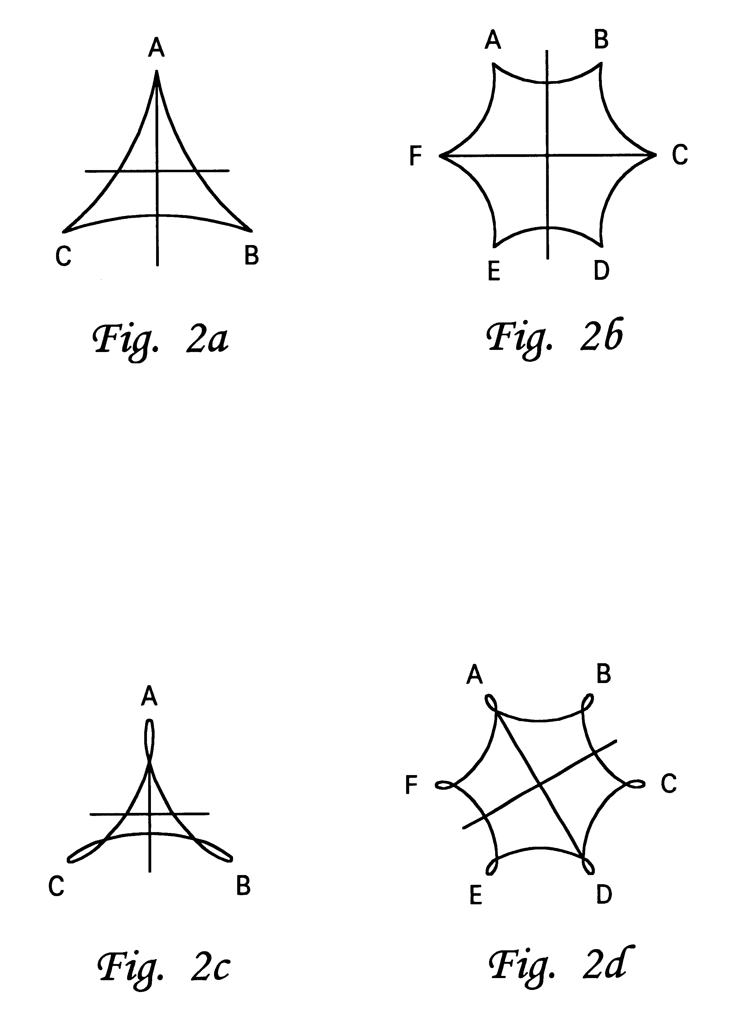
The present inventor has determined surprisingly that certain advantages can be obtained in a planar sputtering magnetron with a rectangular target when the motion of the magnet assembly is repetitive rather than non-repetitive. Non-repetitive motions are supposed to distribute the erosion uniformly over the target area. However, in accordance with the present invention, substantially uniform erosion of the target can be obtained by repetitive, i.e. reentrant, motions in which the same part of the target is eroded at the same time within any cycle of the motion.

In accordance with the present invention complex motions may be produced by a simple single drive mechanism which involves simple moving parts and requires a minimum of feed-throughs ...


PUM

PropertyMeasurementUnit
Fractionaaaaaaaaaa
Fractionaaaaaaaaaa
Fractionaaaaaaaaaa

Abstract

The present invention provides a planar magnetron including a surface for mounting a planar substantially polygonal target (2) having a substantially central target area for sputtering onto a substrate. The magnetron comprises an array of magnets (4) defining a closed loop magnetic field for generating an elongated plasma race-track above the target (2). Means for establishing cyclical, relative, substantially translational movement between the race-track and the target support surface are provided, the substantially translational movement being substantially parallel to this surface and the trace of the substantially translational movement being a two-dimensional figure. The periphery of the race-track lies substantially within said substantially central target area throughout each cycle, the establishing means being adapted to provide a substantially uniform erosion of the target (2) at least within said substantially central target area.

Description

The present invention relates to an improved planar magnetron with a magnet assembly suitable for sputtering or reactive sputtering of materials from a cathode target onto a substrate as well as a method of operating the magnetron.TECHNICAL BACKGROUNDA rectangular planar magnetron with a moveable magnet assembly is known from U.S. Pat. No. 4,444,643, esp. FIGS. 10 and 11 thereof, in which the magnetic assembly is translated laterally and parallel to the major axis of the target. Further, DE-A-27 07 144 proposes a magnet assembly which is swept over a rectangular target along a linear path. As explained in U.S. Pat. No. 4,714,536, these known magnet and target assemblies do not provide a substrate with a satisfactorily uniform sputtered coat nor do they provide a satisfactorily uniform erosion of the target. U.S. Pat. No. 4,714,536 proposes that the magnet assembly is moved with a non-repetitive epicycloidal motion combined with a translational motion over the target, i.e. the magnet...

Claims


Application Information

Patent Timeline
IPC IPC(8): H01J37/32H01J37/34H05H1/46C23C14/35
CPCH01J37/3408H01J37/3455
Inventor DE BOSSCHER, WILMERTCNOCKAERT, DIRK
Owner BEKAERT ADVANCED COATINGS
Why Eureka
Try Eureka