Method and apparatus for asymmetric communication of compressed speech

a communication method and compressed speech technology, applied in the field of vocoder, can solve the problems of reducing the quality of speech signals, additional distortions, and speech quality reduction, and achieve the effects of reducing the rate of packet loss, reducing interference, and increasing bandwidth

Inactive Publication Date: 2001-11-27
MICROSOFT TECH LICENSING LLC
View PDF8 Cites 24 Cited by
  • Summary
  • Abstract
  • Description
  • Claims
  • Application Information

AI Technical Summary

Benefits of technology

The present invention also allows the establishment of asymmetric communication which is an advantage particularly in circumstances where asymmetry exists in the transmission medium. One example is the case of a wireless transmission where the channel characteristics in the forward and reverse directions may be different. If, for example, the forward link suffers from higher levels of interference compared to the reverse link, it is possible to select in the forward link an encoder unit/decoder unit pair operating at a lower bit-rate, thereby allo

Problems solved by technology

The main disadvantage is a reduction in speech quality.
Tandem connections of low bit-rate vocoders are known to cause additional distortions and reduce the quality of the speech signal.
This method of transmitting the speech signals introduces degradation in the speech quality.
However, this solution is only feasible when the two mobile terminals, hence the base stations serving them, employ identical vocoders.
If the two terminals involved in a connection utilize different v

Method used


Image

  • Method and apparatus for asymmetric communication of compressed speech
  • Method and apparatus for asymmetric communication of compressed speech
  • Method and apparatus for asymmetric communication of compressed speech

Examples


Embodiment Construction

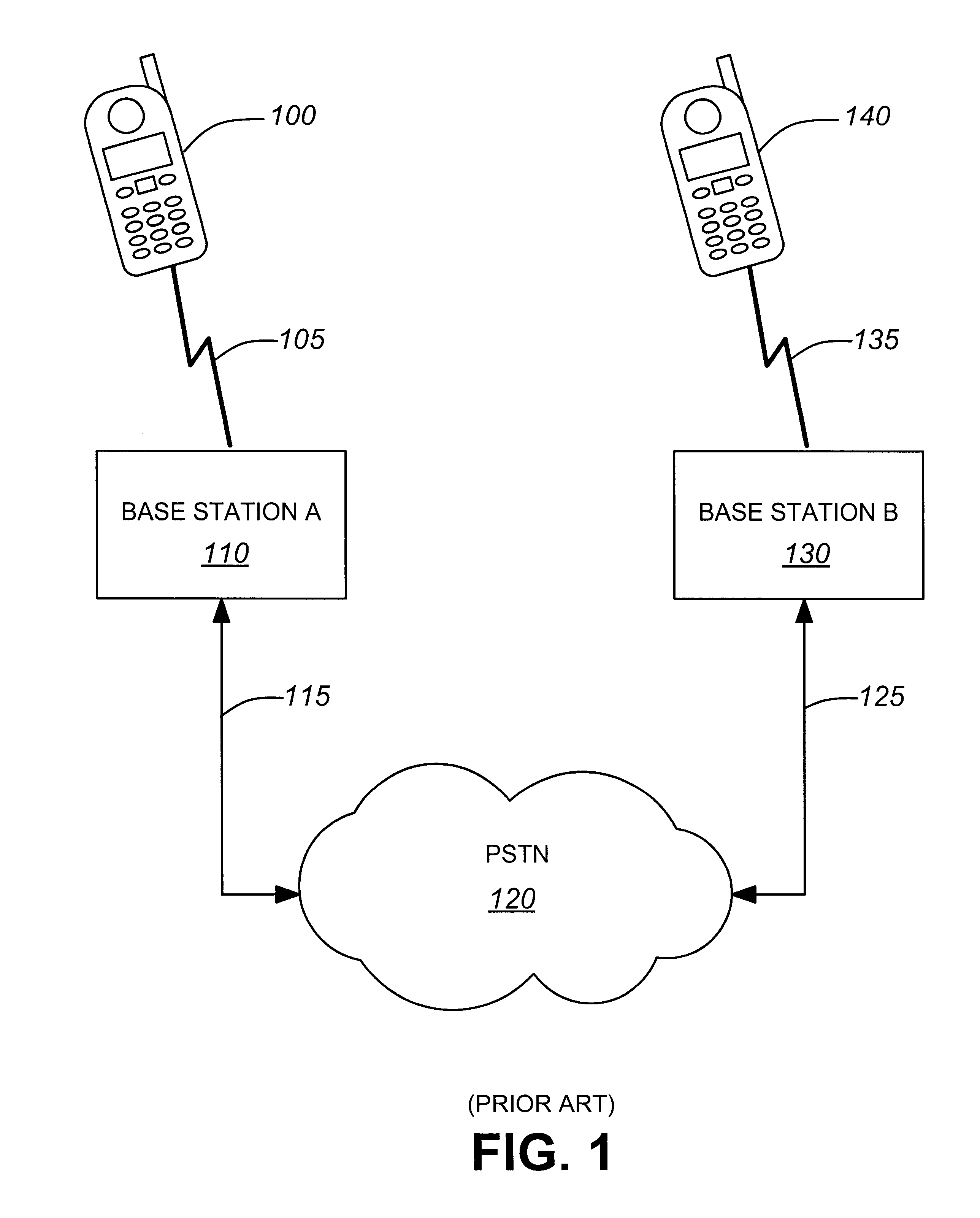
FIG. 1 is a block diagram providing a simplified view of a wireless telecommunications network. FIG. 1 shows a wireless terminal 100 communicating over a wireless link 105 (through an air interface) to a Base Station A (BS A) 110. Wireless link 105 is used to transfer voice data as well as signal and control data. This involves several channels as will be described in detail later. BS A 110 communicates with BS B 140 through the PSTN 120 via physical links 115 and 135 which carry voice data as well as signal and control data. Finally, BS B communicates with wireless terminal 140 over wireless link 135, which is identical to wireless link 105 in this particular embodiment of the invention.

When a call is made to or from a wireless terminal 100 or 140, four radio channels are involved in each of the links 105 and 135 between wireless terminals 100 and 140 and their respective base stations 110 and 130. The channel used to communicate voice data from the BC to the wireless terminal is c...


PUM


Abstract

This invention relates to a method and an apparatus for processing digital audio signals that may reduce the signal degradation occurring when the signal is exchanged between two communication terminals equipped with vocoders in a communication network. The solution proposed by this invention is to provide a communication terminal with a vocoder including a decoder section provided with a plurality of decoding units. A switch activates a selected one of the decoding units in dependence of the format of the compressed audio signal data frames received from a remote communication terminal. This system allows the communication terminal to support a number of different speech compression formals. In order to achieve simplicity and low cost, the communication terminal is provided with a single encoding unit. This results in an asymmetric arrangement where the communication terminal has a large number of decoding units than encoding units. The great majority of the speech compression algorithms deployed in wireless and Internet telephony standards have the property that their speech decoders are of far less computational complexity than their respective speech encoder. Therefore, a low-cost terminal can be produced which supports a low complexity speech encoder unit and a variety of speech decoder units.

Description

This invention relates to a method and an apparatus for processing digitized voice signals in a communications environment that can be of a wireless nature.In recent years, the telecommunications industry has witnessed the proliferation of a variety of digital vocoders in order to meet bandwidth demands of different wireline, and wireless communication systems. The name "vocoder" stems from the fact that its applications are specific to the encoding and decoding of voice signals primarily. Vocoders are usually integrated in mobile telephones and in base stations of the communication network. They are also found on computer sound cards and used for Internet telephony. They provide high compression of a digitized voice signal as well as the reverse transformation while maintaining acceptable speech quality.For the purposes of this specification, the term "vocoder" is defined as a speech coding device that includes two main sections, namely an encoder section and a decoder section. The...

Claims


Application Information

Patent Timeline
IPC IPC(8): G10L19/00
CPCG10L19/00
Inventor RABIPOUR, RAFICOVERDALE, PAULNAVARRO, WILLIAM
Owner MICROSOFT TECH LICENSING LLC
Why Eureka
Try Eureka