Waste incineration machine

a waste incineration machine and waste technology, applied in the direction of capillary burners, combustion types, lighting and heating apparatus, etc., can solve the problems of unsuitable waste incineration machines for small-sized waste incineration machines, increased combustion costs, and reduced combustion efficiency

Inactive Publication Date: 2001-12-04
MEITO
View PDF9 Cites 13 Cited by
  • Summary
  • Abstract
  • Description
  • Claims
  • Application Information

AI Technical Summary

Benefits of technology

The present invention has been made in view of the above-mentioned circumstances, and provides a waste incineration machine which solves these problems, and which is capable of rendering a waste gas discharged during the combustion of waste smokeless and odorless without providing an after-burner.
The present invention also provides a waste incineration machine capable of obtaining hot water by utilizing the heat of a waste gas, reducing the temperature of a waste gas and preventing an increase in an ambient temperature of the incineration machine.

Problems solved by technology

However, since the waste incineration machine disclosed in the former publication requires a secondary combustion chamber and a secondary combustion burner, not only the dimensions of a machine body but also the combustion cost increases.
Therefore, this waste incineration machine is unsuitable to be used as a small-sized waste incineration machine.
Consequently, the waste gas is discharged from the chimney to the outside, and the waste gas goes outside without having received the sufficient radiation of the far infrared rays.
Thus, there is the possibility that the waste gas is not completely burnt and cannot be rendered smokeless.

Method used


Image

  • Waste incineration machine
  • Waste incineration machine
  • Waste incineration machine

Examples


Embodiment Construction

A mode of embodiment of the present invention will now be described with reference to the drawings.

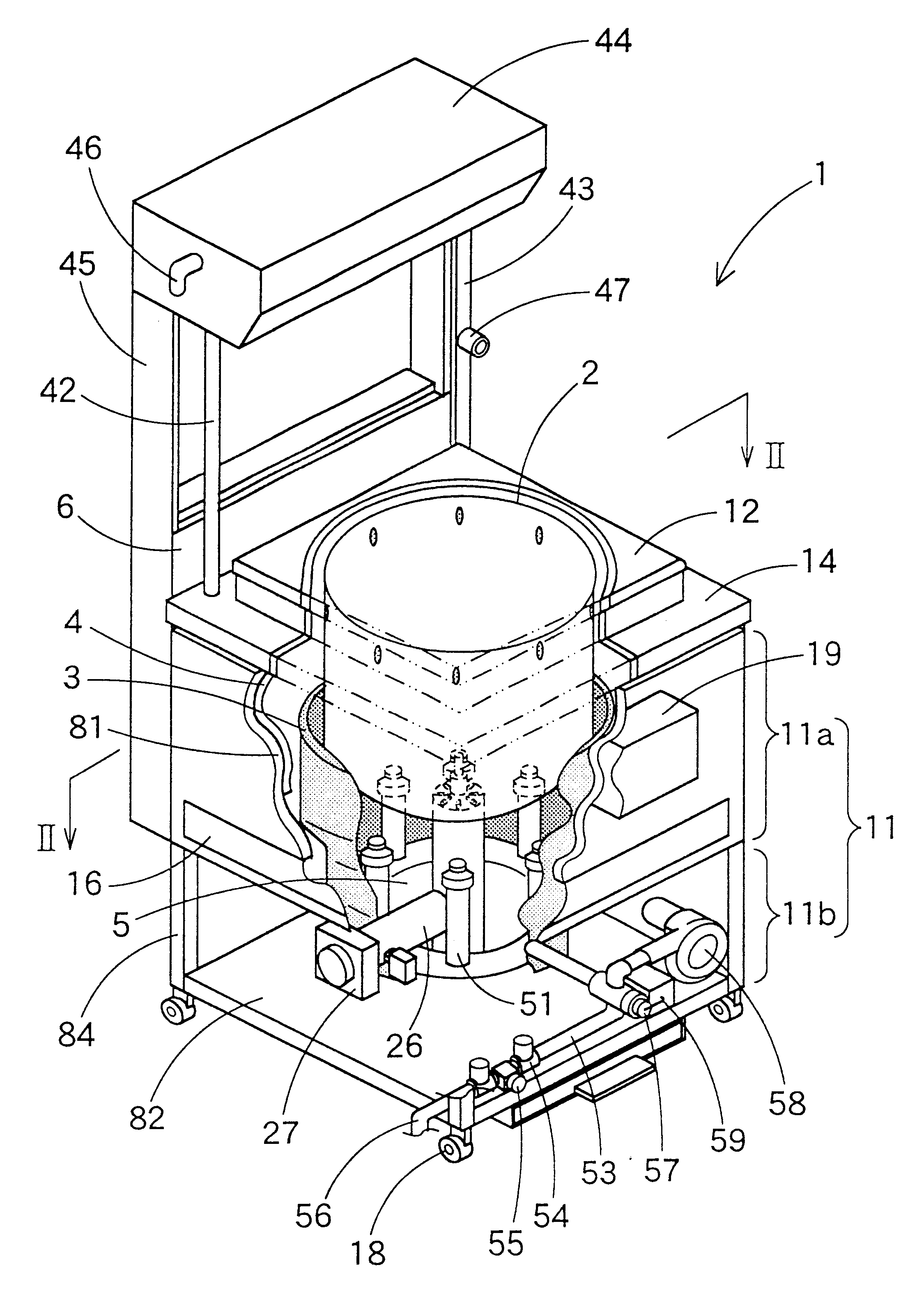
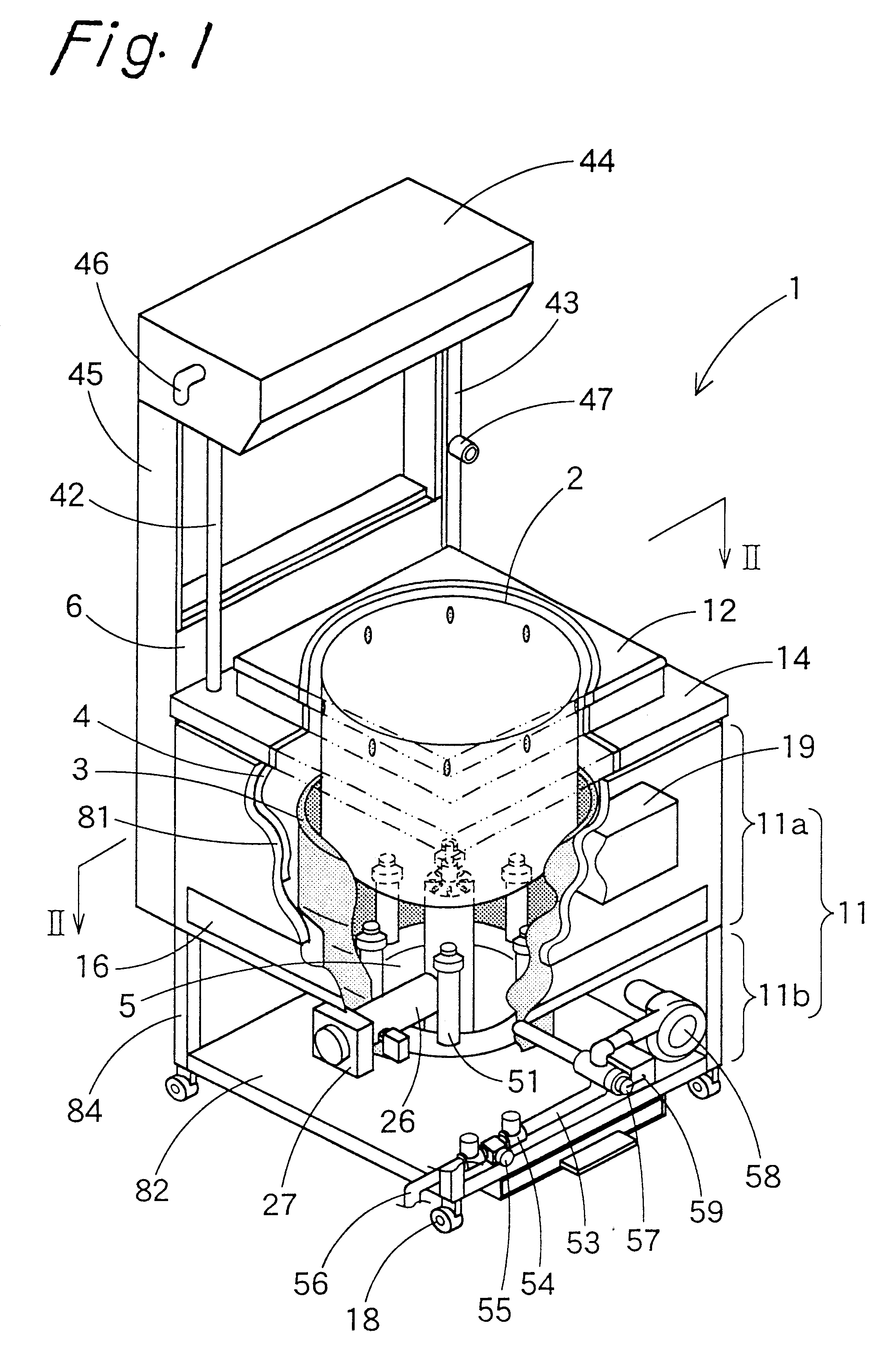
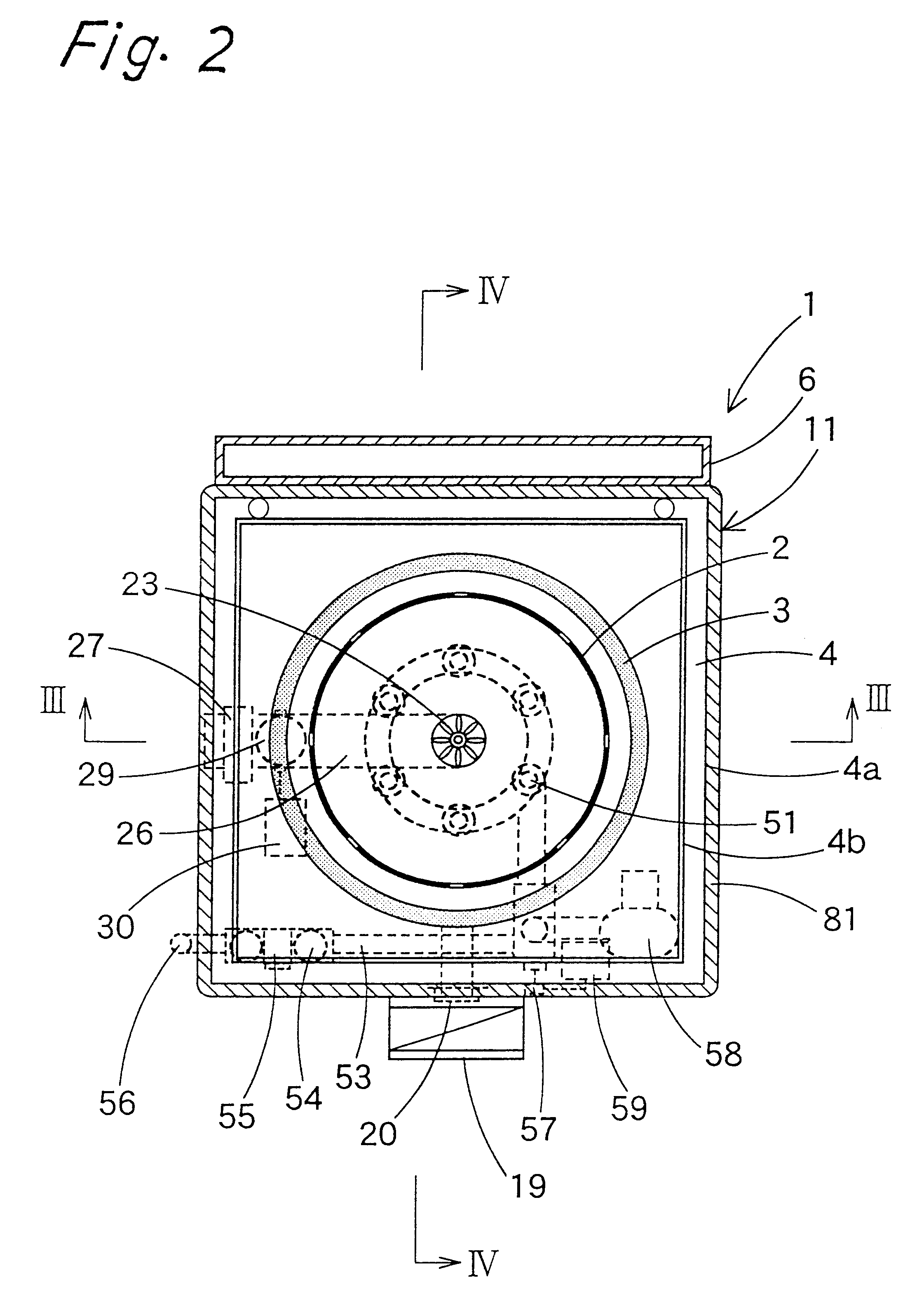
As shown in FIGS. 1-3, a waste incineration machine 1 is formed by providing a combustion furnace 2 installed in an inner portion of a casing 11, a combustion chamber 5 formed under the combustion furnace 2, a heat insulating wall 3 surrounding the combustion furnace 2 and combustion chamber 5 with a predetermined space left therebetween, a heat exchanger 4 surrounding the heat insulating wall 3 with a predetermined space left therebetween, and a blower 27 adapted to blow the air into the combustion furnace 2. The waste incineration machine 1 is further provided with an openable cover 12 enclosing an upper surface of the casing 11, a covering member 14 supporting the openable cover 12, an exhaust cylinder 6 disposed adjacently to a rear surface of the casing 11, and a tank 44 disposed above the exhaust cylinder 6 and joined to the heat exchanger 4.

The casing 11 is made of stainless ste...


PUM


Abstract

A waste incineration machine capable of rendering a waste gas occurring during the combustion of waste smokeless and odorless. A heat insulating wall to which a first far infrared ray radiator is fixed is provided so as to surround a combustion furnace and a combustion chamber, and a heat exchanger so as to surround the heat insulating wall. An inner flue is formed between the heat insulating wall and combustion furnace, and an outer flue serving as a waste gas convection chamber between the heat insulating wall and heat exchanger. An upper part of a communication portion between the inner and outer flues is covered with a heat insulating member constituting a second far infrared ray radiator so as to subject the waste gas to secondary heating using far infrared rays, and thereby to render the waste gas smokeless and odorless. Preferably, the heat insulating wall is formed into a substantially cylindrical shape, and the heat exchanger into a rectangular box-shape open at the top and the bottom, whereby the volume of the outer flue is increased to thereby lengthen the time for circulating the waste gas by convection.

Description

BACKGROUND OF THE INVENTION1. Field of the InventionThis invention relates to a waste incineration machine for burning mainly garbage, and more particularly to a small-sized waste incineration machine capable of removing smoke and odor occurring during the combustion of waste.2. Description of the Related ArtThe techniques for secondarily burning a waste gas, which occurs when waste is burnt, by an after-burner provided so as to render the waste gas smokeless and odorless have heretofore been known. These techniques include as shown in, for example, Japanese Patent Laid-Open No. 225,015 / 1995, the techniques for providing a secondary combustion burner in a secondary combustion chamber connected to a primary combustion chamber, and completely burning a waste gas, which occurs in the primary combustion chamber, by the secondary combustion burner so as to render the waste gas smokeless.The techniques for providing a far infrared ray radiant material in an incineration machine, and secon...

Claims


Application Information

Patent Timeline
Patent Type & Authority Patents(United States)
IPC IPC(8): F23G5/08F23G5/12F23M9/00F23G5/00F23G5/14F23J15/00
CPCF23G5/12F23G2202/70
Inventor FURUTA, SATOSHI
Owner MEITO
Why Eureka
Try Eureka