Complete blade and wafer handling and support system without tape

a support system and complete technology, applied in the field of wafer handling and support systems, can solve the problems of accelerating blade wear accelerating blade wear and "gumming up" of the cutting blade,

Inactive Publication Date: 2001-12-04
MICRON TECH INC
View PDF21 Cites 4 Cited by
  • Summary
  • Abstract
  • Description
  • Claims
  • Application Information

AI Technical Summary

Benefits of technology

The present invention provides several advantages over prior art techniques. Yields are increased in comparison to systems that use adhesive tape. Yields are also increased in comparison to systems that require a specialized patterned chuck corresponding to each particular die to be cut. The method of the present invention may be carried out using much of the existing wafer handling equipment. Also, the life of the cutting blade is increased which, in turn, reduces the amount of down time of the dicing process and thus increases output. Those advantages and benefits, and others, will be apparent to those of ordinary skill in the art from the Description of a Preferred Embodiment, herein below.

Problems solved by technology

That damages the cutting blade, accelerates blade wear, and necessitates premature blade replacement to insure that wafers are not damaged during dicing.
The adhesive binds to the cutting blade, causing accelerated blade wear and "gumming up" of the cutting blade.
A gummed-up cutting blade reduces the effectiveness of the cutting blade, increases friction between the cutting blade and the wafer, and increases the tendency of the cutting blade to bind and break.
In addition, the risk of the cutting blade binding increases as the temperature of the cutting blade increases.
Furthermore, the silicon substrate may be damaged by the heat.
As a result, the heat generated by the dicing process, and all of the undesirable side effects of the heat, limits the rate at which the cutting blade can be moved across a wafer.
As the rate of the dicing processes decreases, the amount of time required to dice a wafer increases.
The accelerated wear and damage caused to cutting blades from contact with the chuck and the adhesive requires that they be replaced after dicing only about five or six wafers.
The continued use of a worn cutting blade may result in damaged or totally destroyed wafers caused by a cutting blade breaking and spraying debris across the wafer.
Replacing cutting blades is expensive not only in terms of the costs of the cutting blade, but also in terms of down time of the dicing process and interruption of the fabrication process while an old cutting blade is being removed and a new cutting blade is being installed.

Method used


Image

  • Complete blade and wafer handling and support system without tape
  • Complete blade and wafer handling and support system without tape
  • Complete blade and wafer handling and support system without tape

Examples


Embodiment Construction

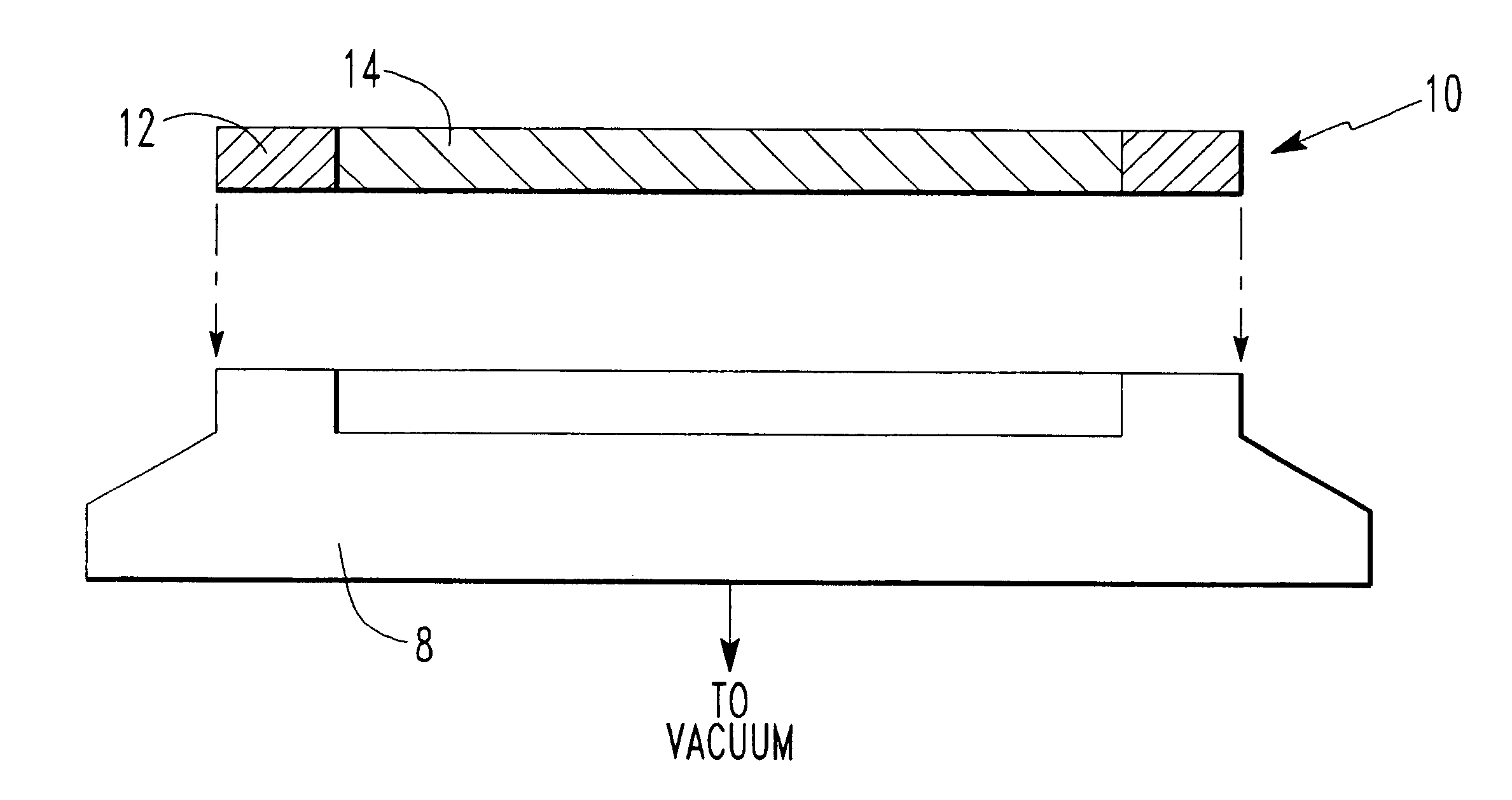
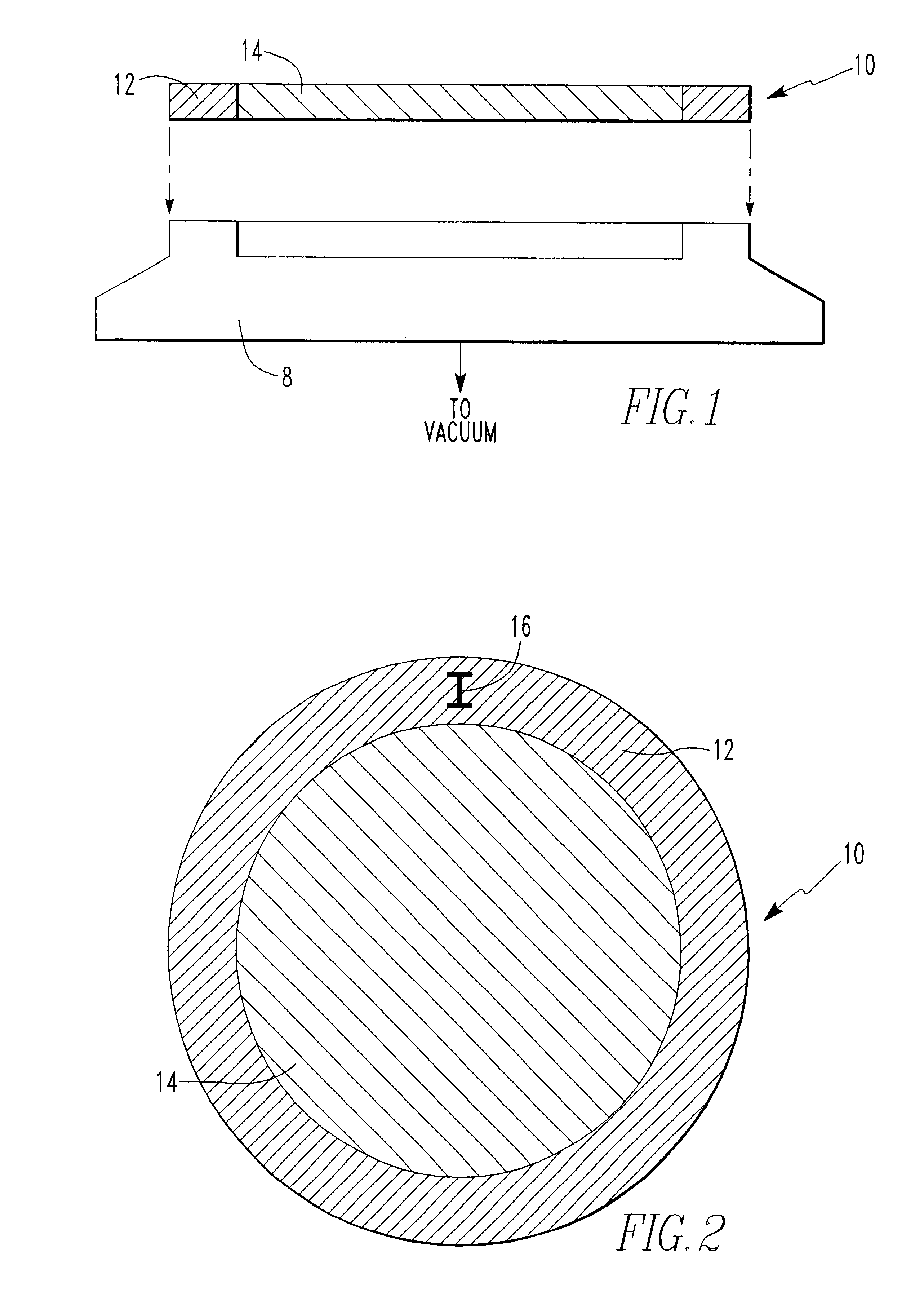
FIG. 1 is a cross sectional view of a chuck plate 10 constructed in accordance with the present invention in combination with a standard wafer chuck 8. The chuck plate 10 comprises a non-porous section 12 surrounding a porous section 14. The chuck plate 10, non-porous section 12 and porous section 14 are each preferably circular, although they may each also be other shapes. The chuck plate 10 is designed to support a wafer (not shown), wherein the wafer is preferably positioned so that the entire wafer rests on the porous section 14. The chuck plate 10 is designed to be positioned in combination with a standard wafer chuck 8 which standard wafer chuck 8 is attached to a vacuum pump. When a vacuum force is applied by the vacuum pump to the standard wafer chuck 8, that vacuum force is, in turn, applied to the chuck plate 10. The vacuum force passes through the porous section 14 of the chuck plate 10 which causes the wafer to be held securely to the porous section 14 of the chuck plate...


PUM

PropertyMeasurementUnit
thickaaaaaaaaaa
porosityaaaaaaaaaa
porosityaaaaaaaaaa

Abstract

The wafer handling and support system disclosed herein does not use tape and is adapted for use in conjunction with a number of work stations. The wafer handling and support system includes a chuck plate comprised of a non-porous section surrounding a porous section and a robotic arm for transporting a chuck plate / wafer combination under vacuum. The chuck plate is sized to be carried by a wafer chuck and the porous section of the chuck plate is configured to support a wafer. The wafer may be held in place on the chuck plate by the application of a vacuum.

Description

1. Field of the InventionThe invention relates generally to wafer handling and support systems and, more specifically, to wafer handling and support systems which do not use tape.2. Description of the BackgroundMany different types of semiconductor processing systems require the use of wafer handling systems or wafer support systems. Wafers are comprised of a number of integrated circuits or "dice". Through a dicing process, the dice are cut from the wafer. Traditionally, the dicing process is performed with wafer spindle and blade assemblies having circular cutting blades. Such devices may be obtained commercially from Disco Hi Tec America, Inc., Santa Clara, Calif. The cutting blades are oftentimes nickel-plated with a diamond grit cutting edge to allow for smooth cuts with a minimum amount of splintering of the wafer itself.It is well known in the art to place the wafers on a surface, known as a "cutting chuck", where the wafers are diced by a cutting blade. During the dicing pro...

Claims


Application Information

Patent Timeline
Patent Type & Authority Patents(United States)
IPC IPC(8): B28D5/00
CPCB28D5/0082B28D5/0094
Inventor FARNWORTH, WARREN M.
Owner MICRON TECH INC
Why Eureka
Try Eureka