Plate-shaped compression mold, process for producing the same and process for making laminate therewith

a plate-shaped compression mold and plate-shaped technology, applied in the direction of circuit susbtrate materials, circuit precursor manufacture, soldering auxiliaries, etc., can solve the problems of the comparatively low thermal coefficient of linear expansion of the pressing plate material, which is about 10.0.times.10.sup.-6/k to 13, -6/k at room temperatur

Inactive Publication Date: 2001-12-11
BOHLER BLECHE GMBH
View PDF3 Cites 7 Cited by
  • Summary
  • Abstract
  • Description
  • Claims
  • Application Information

AI Technical Summary

Problems solved by technology

A great disadvantage of these pressing plate materials is their comparatively low thermal coefficient of linear expansion of about 10.0.times.10.sup.-6 / K to 13.0.times.10.sup.-6 / K at room temperature.
This difference in expansion behavior of the mold and the coating of the laminate upon heating to the curing temperature of the resin can result in warping and wrinkling of the copper foil and make such printed circuit boards unusable.
While wrinkles and warping of the coating foil during curing of the laminate resin due to a temperature increase during molding can be avoided with these mold materials, the service life of such pressing plates is short.
This disadvantage is caused by the fact that, due to the low hardness as well as the flow characteristics under local pressure stress of these materials and because of their low wear resistance, dents caused, for example, by foreign bodies, such as grains of dust and the like and / or borders or edges of the laminate, may be formed in the working surface.
During compression of the next circuit board, these dents create a bump on the metal coating which is disadvantageous since upon etching of the conductors the Ohmic resistance in the corresponding layer area will differ from that in the rest of the layer.

Method used


Image

  • Plate-shaped compression mold, process for producing the same and process for making laminate therewith
  • Plate-shaped compression mold, process for producing the same and process for making laminate therewith

Examples


Embodiment Construction

The particulars shown herein are by way of example and for purposes of illustrative discussion of the embodiments of the present invention only and are presented in the cause of providing what is believed to be the most useful and readily understood description of the principles and conceptual aspects of the present invention. In this regard, no attempt is made to show structural details of the present invention in more detail than is necessary for the fundamental understanding of the present invention, the description taken with the drawings making apparent to those skilled in the art how the several forms of the present invention may be embodied in practice.

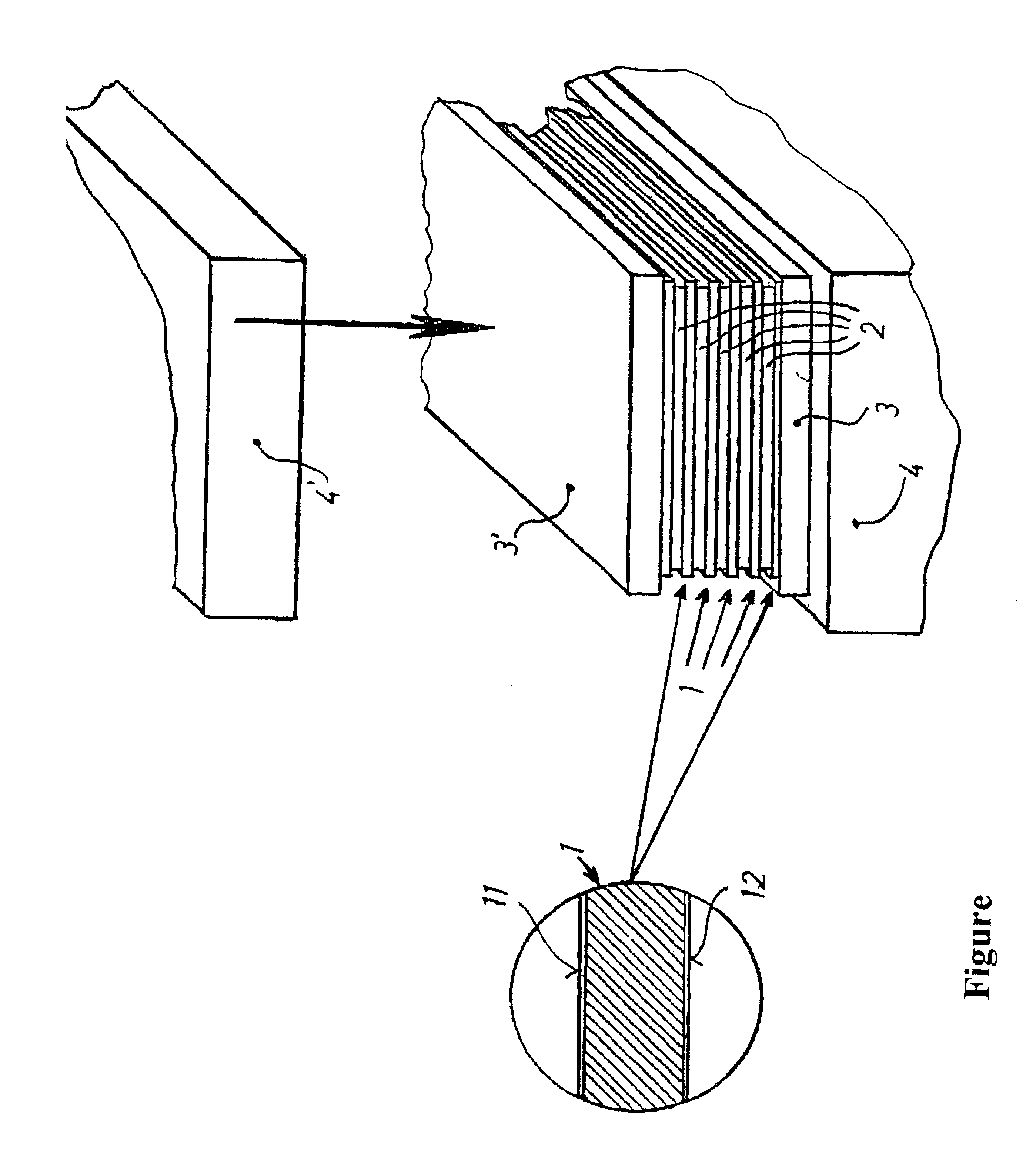
The FIGURE illustrates an embodiment of a compression mold according to the present invention. In particular, the compression mold comprises a bottom pressing plate 3 and a top pressing plate 3', as well as lower and upper press members 4 and 4' for pressing the pressing plates 3 and 3' against the (multilayer) laminate 1. The ...


PUM

PropertyMeasurementUnit
thicknessaaaaaaaaaa
thicknessaaaaaaaaaa
thicknessaaaaaaaaaa

Abstract

A plate shaped compression mold, a process for producing the same and a process for making laminate therewith. The plate-shaped compression mold for producing sheet laminate including synthetic resin with a metal coating on at least one surface thereof has a surface for contacting the metal coating of the sheet laminate, which surface has a Rockwell C hardness of higher than about 44 and a thermal coefficient of linear expansion which differs from that of the metal coating by not more than about 2.5x10⁻⁶/K, thereby substantially preventing warping or wrinkling of the metal coating during the compression molding process.

Description

The present application claims priority under 35 U.S.C. .sctn. 119 of Austrian Patent Application No. 82 / 99, filed on Jan. 21, 1999.1. Field of the InventionThe present invention relates to a plate-shaped compression mold for producing sheet laminates made of synthetic resins and having a metal coating on at least one surface thereof. In addition, the invention relates to a process for producing a pressing plate of a plate-shaped compression mold, and a process for producing sheet laminates, in particular printed circuit boards with copper coatings, wherein a corresponding compression mold is employed.2. Discussion of Background InformationTechnical laminates are flat elements, produced by stacking and thermal compression molding of substrates, which are impregnated with synthetic resin, for example, phenolic resin. Paper, fiber mats, such as glass fiber mats, and the like can be used as substrates. The curing process of the synthetic resin at high temperature can take place in seve...

Claims


Application Information

Patent Timeline
Patent Type & Authority Patents(United States)
IPC IPC(8): B30B15/06C23C30/00H05K3/02B21D37/20B29C43/18B29C43/32B32B15/08B32B37/10F04B25/04H05K1/03
CPCB30B15/064C23C30/00H05K3/022B32B37/10Y10T428/12993H05K2201/068Y10S428/926Y10S428/94Y10T428/12007Y10T428/12944Y10T428/12937Y10T428/12229Y10T428/12986Y10T428/12854Y10T428/12139Y10T428/31678F04B25/04
Inventor KUGLER, ALFREDJERLICH, WERNER JOSEF
Owner BOHLER BLECHE GMBH
Why Eureka
Try Eureka