

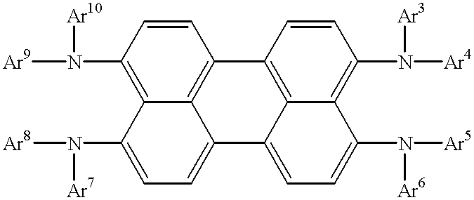
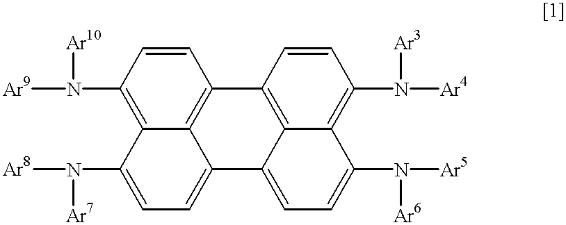
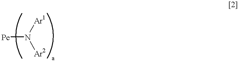
Compound for organic electro-luminescence device and organic electro-luminescence device using the compound
a technology of organic electroluminescence and compound, which is applied in the direction of discharge tube luminescnet screen, anthracene dye, etc., can solve the problems of low light emission efficiency, high driving voltage, and deterioration of conventional organic el devices in properties to a great exten
- Summary
- Abstract
- Description
- Claims
- Application Information
AI Technical Summary
Problems solved by technology
Method used
Image

Examples
example 1
Compound (53) was dissolved in methylene chloride, and the solution was spin-coated on a cleaned glass substrate with an ITO electrode to form a hole-injecting type light-emitting layer having a thickness of 50 nm. Then, gallium bis(2-methyl-8-hydroxyquinolinate)(1-naphtolate) complex was vacuum-deposited to form an electron-injecting layer having a thickness of 40 nm, and an electrode having a thickness of 100 nm was formed thereon from a magnesium / silver alloy having a magnesium / silver mixing weight ratio of 10 / 1, to obtain an organic EL device. The light-emitting layer and the electron-injecting layer were formed by deposition under a vacuum of 10.sup.-6 Torr at a substrate temperature of room temperature. The device showed a red light emission having a light emission brightness of 150 (cd / m.sup.2) at a direct current voltage of 5 V, a maximum light emission brightness of 2,200 (cd / m.sup.2) and a light emission efficiency of 0.40 (1 m / W).
example 2
4,4'-bis[N-(1-naphthyl)-N-phenylamino]biphenyl(.alpha.-NPD) was vacuum-deposited on a cleaned glass substrate with an ITO electrode to form a hole-injecting layer having a thickness of 30 m. Then, Compound (49) as a light-emitting material was vacuum-deposited to form a light-emitting layer having a thickness of 30 nm. Further, gallium bis(2-methyl-8-hydroxyquinolinate)(phenolate) complex was vacuum-deposited to form an electron-injecting layer having a thickness of 30 nm. An electrode having a thickness of 100 nm was formed thereon from a magnesium / silver alloy having a magnesium / silver mixing weight ratio of 10 / 1, to obtain an organic EL device. The hole-injecting layer and the light-emitting layer were formed by deposition under a vacuum of 10.sup.-6 Torr at a substrate temperature of room temperature. The device showed a red light emission having a light emission brightness of 200 (cd / m.sup.2) at a direct current voltage of 5 V, a maximum light emission brightness of 5,000 (cd / m...
example 3
4,4',4"-tris(N-(3-methylphenyl)-N-phenylamino)triphenylamine was vacuum-deposited on a cleaned glass substrate with an ITO electrode to form a hole-injecting layer having a thickness of 40 nm. Then, .alpha.-NPD was vacuum-deposited to form a second hole-injecting layer having a thickness of 10 nm. Further, Compound (61) was vacuum-deposited to form a light-emitting layer having a thickness of 30 nm. Further, gallium bis(2-methyl-8-hydroxyquinolinate)(1-phenolate) complex was vacuum-deposited to form an electron-injecting layer having a thickness of 30 nm. An electrode having a thickness of 150 nm was formed thereon from an aluminum / lithium alloy having an aluminum / lithium mixing weight ratio of 25 / 1, to obtain an organic EL device. The hole-injecting layers and the light-emitting layer were formed by deposition under a vacuum of 10.sup.-6 Torr at a substrate temperature of room temperature. The device showed a red light emission having a light emission brightness of 210 (cd / m.sup.2)...
PUM
| Property | Measurement | Unit |
|---|---|---|
| DC voltage | aaaaa | aaaaa |
| brightness | aaaaa | aaaaa |
| melting point | aaaaa | aaaaa |
Abstract
Description
Claims
Application Information