
Methods and apparatus for generating a plasma torch

a plasma torch and plasma technology, applied in plasma welding apparatus, welding apparatus, manufacturing tools, etc., can solve the problems of large structure of inductive torch and therefore unsuitability for certain applications, and achieve the effect of easy mounting, small size, and easy starting of plasma sour

Inactive Publication Date: 2001-12-11
POLYTECHNIC INST OF NEW YORK
View PDF9 Cites 65 Cited by
  • Summary
  • Abstract
  • Description
  • Claims
  • Application Information

AI Technical Summary

Benefits of technology

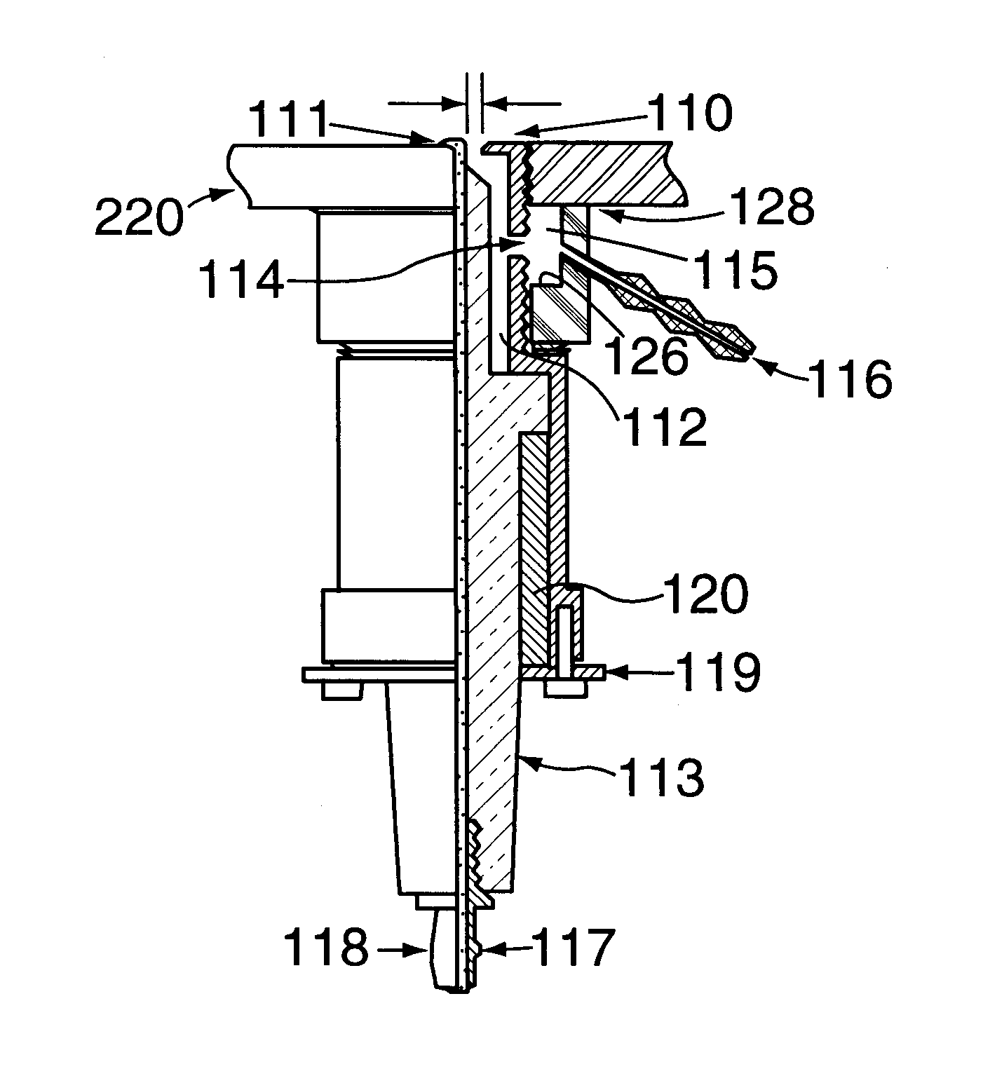
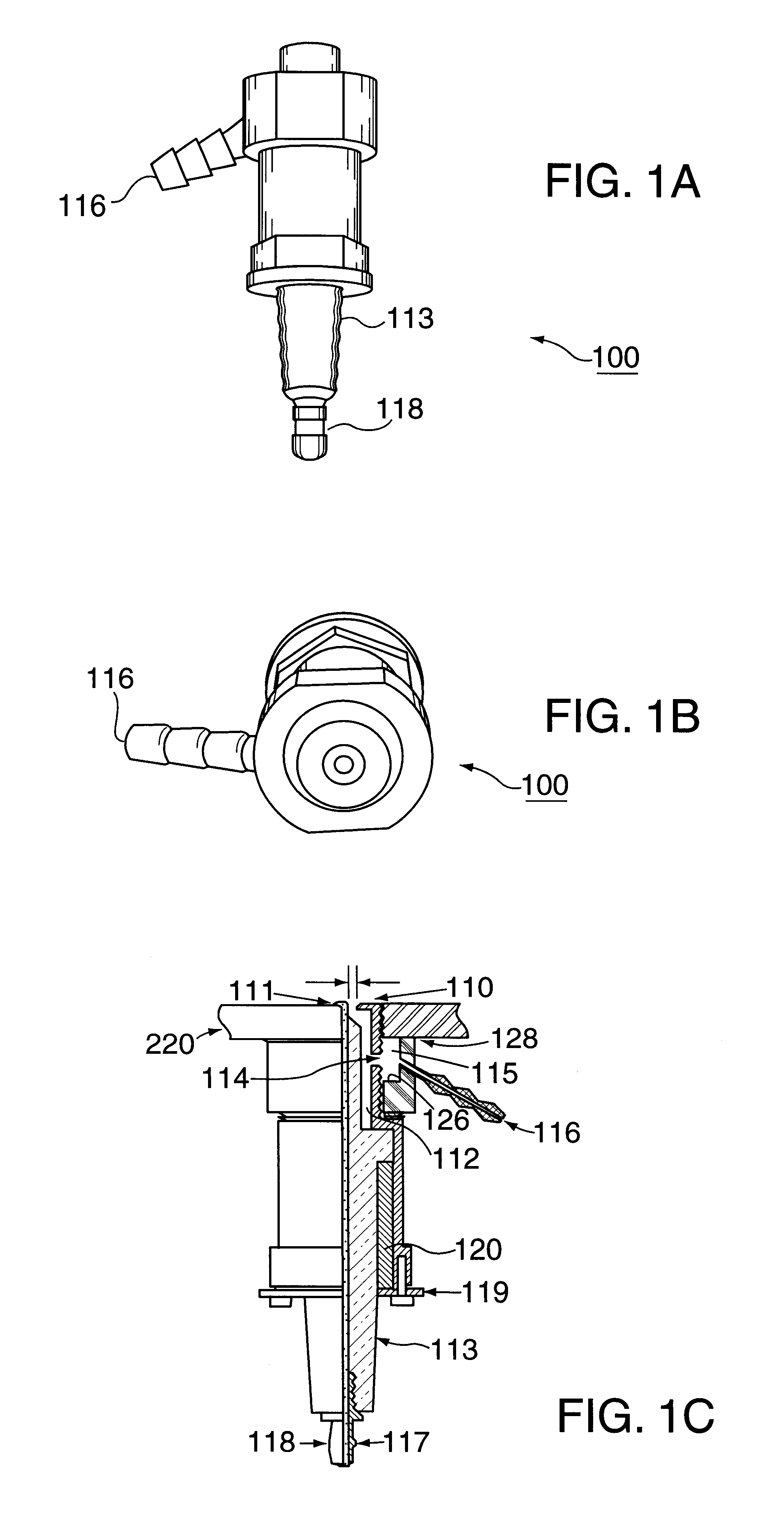
The present invention meets the aforementioned goals by providing a capacitive plasma torch employing a pair of electrodes to apply a high voltage, supplied directly from a power supply, for a discharge. Its compact size (e.g., the size of a standard motor vehicle's spark plug) permits it to be used in many applications where a relatively small size is desired or required.
The plasma torch of the present invention may be constructed using components from available spark plugs. In one embodiment, each plasma torch module can produce a torch plasma having a radius of about 1 cm and larger and a height of about 6 cm, and a peak density exceeding 10.sup.13 electrons / cm.sup.3. The plasma source can easily start the generation of a plasma source quickly.
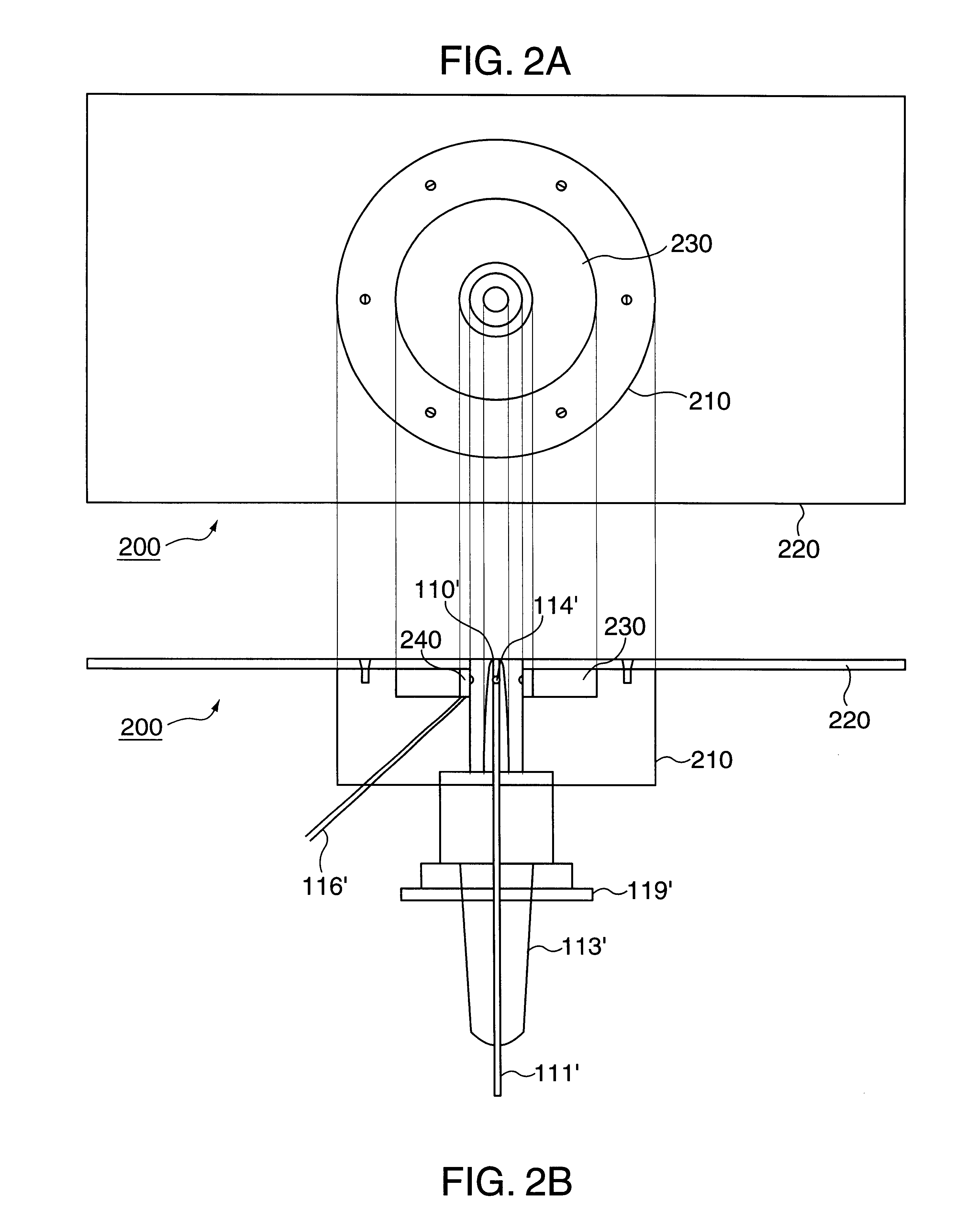
The plasma torch of the present invention can be easily mounted on a plate, which may or may not have a curvature. Thus, the plasma torch of the present invention can be arranged in an array, for example. In this way, a set of modules, each connected in series, with a ballasting capacitor in the circuit, can be operated as an array sharing a common power source to produce a dense and large volume plasma.
The present invention is attractive in that its electrical circuitry is simple and is adaptable to a number of AC power sources, such as 60 Hz voltage available at most common wall outlets.
By providing a plasma torch module having the size of a spark plug and in the form of a modular unit, which can be installed onto (e.g., screwed into) the surface (e.g., grounded) of an object as an array, the shape of the base surface of the array can be easily adjusted for each specific application. Further, by using the module as a building block, the design of large volume plasma sources is simplified.

Problems solved by technology

Consequently, the structure of an inductive torch is relatively large and is therefore unsuitable for certain applications.

Method used


Image

  • Methods and apparatus for generating a plasma torch
  • Methods and apparatus for generating a plasma torch
  • Methods and apparatus for generating a plasma torch

Examples


Embodiment Construction

The present invention involves novel methods and apparatus for generating a plasma torch. The following description is presented to enable one skilled in the art to make and use the invention, and is provided in the context of particular applications and their requirements. Various modifications to the disclosed embodiments will be apparent to those skilled in the art, and the general principles set forth below may be applied to other embodiments and applications. Thus, the present invention is not intended to be limited to the embodiments shown.

In the following, functions which may be performed by the present invention are introduced in .sctn. 4.1. Then, structures of apparatus built in accordance with the present invention are described in .sctn. 4.2. Thereafter, operations of the apparatus are described in .sctn. 4.3. Finally, conclusions about the present invention are presented in .sctn. 4.4.

.sctn. 4.1 FUNCTIONS OF THE INVENTION

The present invention may be used to generate a pl...


PUM

PropertyMeasurementUnit
Radiusaaaaaaaaaa
Radiusaaaaaaaaaa
Widthaaaaaaaaaa

Abstract

A modular system for constructing an atmospheric pressure plasma source. A plasma torch module may be constructed by reassembling the structural components of two (2) different models of spark plugs. Each module can produce a plasma torch having a radius of about 1 cm or more, a height of about 6 cm, and a peak density exceeding 1013 cm-3. A set of modules, each connected in series, may be used with a ballasting capacitor such that an array can be operated while sharing a common power supply to produce a plasma having a relatively large volume and a relatively high density. A system having a number of plasma torch modules may be used in applications for absorbing radiation, reducing air drag and igniting fuel.

Description

.sctn. 1. BACKGROUND OF THE INVENTION.sctn. 1.1 Field of the InventionThe present invention concerns methods and apparatus for generating a plasma torch. More specifically, the present invention concerns a module for generating a plasma torch and a system, using an array of such modules, for generating a plasma torch. In addition, the present invention also concerns applications for the plasma torch module and the plasma torch generation system..sctn. 1.2 Related ArtThe present invention relates generally to atmospheric pressure plasma generation devices (or "plasma sources"). Atmospheric pressure plasma sources do not need vacuum systems in their setups. They can have open structures, thereby allowing plasma to be exposed directly to the open air. An atmospheric plasma source may be used for reflecting or absorbing microwave radiation (See, e.g., the article: R. J. Vidmar, "On the Use of Atmospheric Pressure Plasmas as Electromagnetic Reflectors and Absorbers," IEEE Trans. Plasma S...

Claims


Application Information

Patent Timeline
IPC IPC(8): B23K10/00
CPCB23K10/006
Inventor KUO, SPENCER P.KORETZKY, EDWARDORLICK, LESTER
Owner POLYTECHNIC INST OF NEW YORK
Learn More