Structure for reinforcing concrete member and reinforcing method

a technology of structural structure and concrete, applied in the direction of building repair, foundation engineering, shock proofing, etc., can solve problems such as noise and vibration, achieve sufficient reinforcing effects, prevent occurrence, and improve the ductility and proof stress of concrete members

Inactive Publication Date: 2001-12-18
NIPPON STEEL CORP
View PDF10 Cites 33 Cited by
  • Summary
  • Abstract
  • Description
  • Claims
  • Application Information

AI Technical Summary

Benefits of technology

A structure for reinforcing a concrete member according to claim 6 is the structure for reinforcing a concrete member according to one of claims 1 to 4, characterized in that said reinforcing member is arranged and joined along the circumferential direction of the concrete member. Thereby, it is possible to reinforce the concrete members such as a column and beam against shearing stress applied thereto.
A structure for reinforcing a concrete member according to claim 7 is the structure for reinforcing a concrete member according to one of Claims 1 to 4, characterized in that said reinforcing member is arranged and joined along the concrete member in the form of a plane or curved surface. Thereby, it is possible to improve the ductility and proof stress of the concrete member in the form of a plane or curved surface against bending stress or shearing stress applied thereto. For example, it is also possible to prevent the occurrence of cracks at the curved surface of a concrete member such as a tunnel linings. In addition, even when the reinforcing member is arranged and joined on only one surface of the concrete member, sufficient reinforcing effects can be obtained. Therefore, it is possible to exert its reinforcing effects in members which have been difficult to reinforce, such as an elevator shaft, exterior wall, staircase, and the like.
A structure for reinforcing a concrete member according to claim 8 is the structure for reinforcing a concrete member according to one of claims 1 to 4, characterized in that said reinforcing member comprises reinforcing fibers aligned in a given direction, and is joined to the surface of the concrete member so that the reinforcing fibers are aligned at an angle to the concrete member. When the reinforcing fibers comprising the reinforcing sheet are aligned at some given angle to the concrete member, the reinforcing sheet exerts functions similar to the functions of a brace. Ductility and proof stress against bending stress or shearing stress applied to the concrete member in the form of a plane or curved surface, such as a floor, wall, and the like, can be improved. Therefore, the earthquake resistance of buildings can be improved. In addition, even when the reinforcing sheet is arranged and joined on only one surface of the concrete member, sufficient effects can be obtained. Therefore, it is possible to reinforce in the members which have been difficult to reinforce, such as an elevator shaft, exterior wall, staircase, and the like.
A reinforcing method of a concrete member according to claim 9 comprising the steps of: joining a fixing anchor comprising a plurality of reinforcing fibers, such as ca...

Problems solved by technology

Moreover, under a reinforcing construction, forming recesses for attaching t...

Method used


Image

  • Structure for reinforcing concrete member and reinforcing method
  • Structure for reinforcing concrete member and reinforcing method
  • Structure for reinforcing concrete member and reinforcing method

Examples


first example

Shearing Reinforcement of a Column and Beam

Hereinbelow, the structure for reinforcing a concrete member and the reinforcing method of the present invention will be explained with reference to the examples in which the structure and the reinforcing method are adopted to columns and beams.

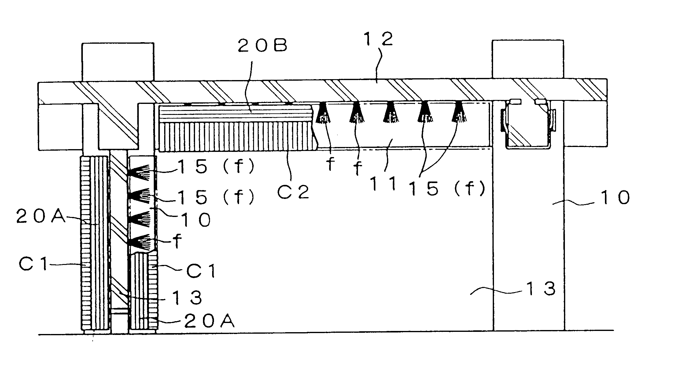
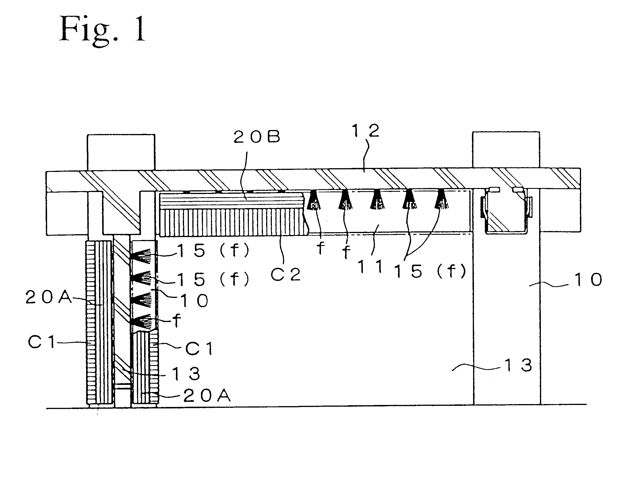
FIG. 1 shows a part of the structure having a reinforced concrete structure or a steel framed reinforced concrete structure. In this figure, reference numeral 10 denotes a column (being a concrete member), reference numeral 11 denotes a beam (being a concrete member), reference numeral 12 denotes a floor formed on the beam 11, and reference numeral 13 denotes a wall.

As shown in FIG. 1, the column 10 is integrally joined to the wall 13. On the top surface of the beam 11, the floor 12 is integrally formed.

In order to reinforce the column 10 and the beam 11 against shearing stress, reinforcing sheets C1 and C2 are arranged and joined to the column 10 and the beam 11. These reinforcing sheets (reinforcin...

second example

Bending Reinforcement of a Beam

As shown in FIG. 7, in order to reinforce the beam 11 against bending stress applied thereto, the reinforcing sheet (reinforcing member) C4 is attached to the under surface of the beam 11. The reinforcing sheet C4 comprises reinforcing fibers, such as carbon fibers, aramid fibers, glass fibers, and the like. The fiber direction (corresponding to the weaving direction when the reinforcing fibers are in the form of a cloth) of the reinforcing sheet C4 is set to the beam direction so that reinforcing effects in the longitudinal direction.

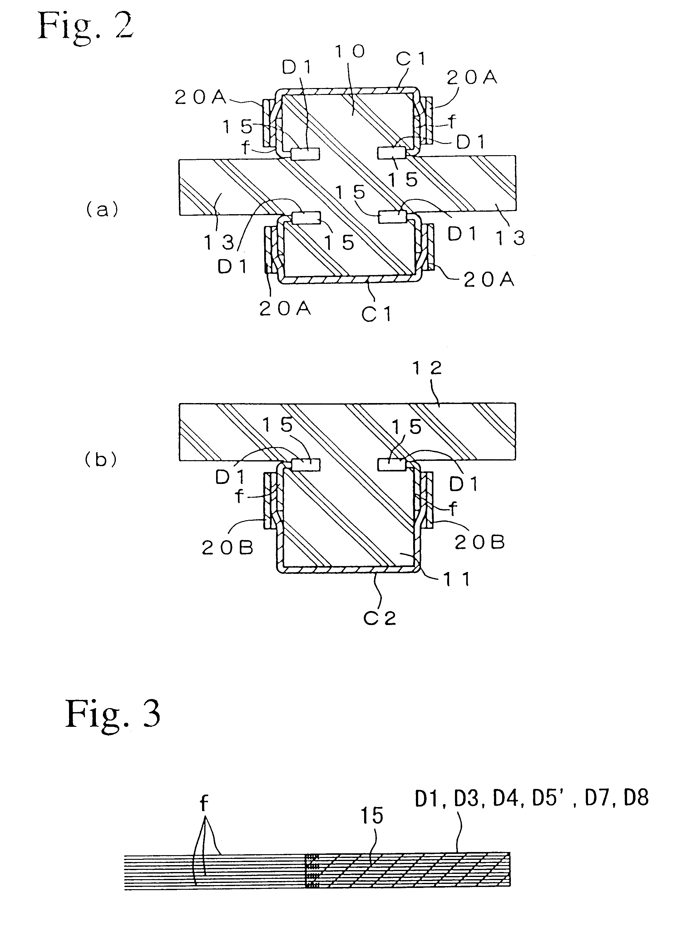
Both edges of the reinforcing sheet C4 are joined by the fixing anchors D3. As shown in FIG. 3, the fixing anchor D3 comprises a large amount of reinforcing fibers f, such as carbon fiber, aramid fiber, glass fiber, and the like, and is obtained by bundling the reinforcing fibers at a bundled portion 15 on the proximal end part side using an adhesive or resin, for example. The reinforcing fiber f are not bundled on the di...

third example

Bending Reinforcement of a Column

As shown in FIG. 8, in order to reinforce the column 10 against bending stress applied thereto, the reinforcing sheets C6 comprising reinforcing fibers, such as carbon fibers, aramid fibers, glass fibers, and the like are respectively joined to all side surfaces of the column 10 so as to extend along the continuous direction, that is the vertical direction of the column 10. The top and bottom ends of the reinforcing sheet C6 are joined by the fixing anchors D4.

As shown in FIG. 5, the fixing anchor D4 comprises a large amount of reinforcing fiber F such as C.F., A.F., G.F. The center part of the fixing anchor is bundled with some crip or the like but both ends are free of bundles and can be spread.

After the fixing anchor D4 is impregnated with resin adhesives or the like, the anchor is inserted into the hole. And the both ends are respectively spread just like FIG. 8. After curing, the reinforcing fiber sheet C6 is applied onto the column 10 with the ...


PUM

PropertyMeasurementUnit
Angleaaaaaaaaaa
Structureaaaaaaaaaa

Abstract

In the structure for reinforcing a concrete member and the reinforcing method of the present invention, a reinforcing sheet is arranged and joined to a various kinds of concrete member, such as column, beam, wall, floor, and the like, by applying the reinforcing sheet to the surface of the concrete member and attaching to the fixing anchors joined to the concrete member or the other concrete member surrounding the concrete member. The fixing anchor comprises a large amount of reinforcing fiber, and is obtained by bundling a part of the reinforcing fiber. The unbundled portion of the fixing anchor is spread along the surface of the concrete member. The reinforcing sheet is over-lapped to the unbundled portion using resin adhesives. In addition, reinforcing fibers, such as carbon fiber, aramid fiber, glass fiber, and the like are preferably used as the material comprising the fixing anchor and reinforcing sheet. Thereby, the reinforcing member can be joined via the fixing anchor to the concrete members. Therefore, it is possible to securely join the edges of the reinforcing member, and reliably exert the reinforcing effects on the concrete member.

Description

The present invention relates to a structure for reinforcing a concrete member and a reinforcing method which are suitable for reinforcing various concrete members.As one conventional method for reinforcing a concrete member having a reinforced concrete structure or a steel framed reinforced concrete structure, such as a column, beam, bent, and stack, there is a method in which a reinforcing sheet made of reinforcing fibers, such as carbon fibers, aramid fibers, glass fibers, or the like is arranged and attached on the surface of the concrete member. In this method, in order to reinforce the concrete member against bending stress applied thereto, the reinforcing sheet is arranged and attached along the concrete member. In order to reinforce the concrete member against shearing stress applied thereto, the reinforcing sheet is arranged and attached so as to wrap around the concrete member.In order to stably fix the reinforcing sheet onto the surface of the concrete member, an adhesive...

Claims


Application Information

Patent Timeline
IPC IPC(8): E04G23/02E04C5/07E04H9/02
CPCE04C5/07E04G23/0218E04H9/02E04G2023/0251E04G23/0225E04G2023/0262E04H9/021E04G23/02
Inventor JINNO, YASUOSAITO, HIDETOTSUKAGOSHI, HIDEOIKETANI, JUN'ICHIFUJITA, TADAOSAWAIDE, MINORUINADA, YASUOSHIMIZU, YOSHIHIKO
Owner NIPPON STEEL CORP
Why Eureka
Try Eureka