Acoustic device

a technology of acoustic devices and acoustic waves, applied in the direction of electromechanical transducers, transducer casings/cabinets/supports, electromechanical transducers, etc., can solve the problems of limited loudness, unavoidably high directionality, and large volume, and achieve rapid spreading or augmenting the build-up of bending wave action. , the effect of beneficial effects

Inactive Publication Date: 2001-12-18
NEW TRANSDUCERS LTD
View PDF48 Cites 386 Cited by
  • Summary
  • Abstract
  • Description
  • Claims
  • Application Information

AI Technical Summary

Benefits of technology

Another useful criterion, and aspect of the invention relative to shape(s) and proportioning of said transverse extents of members hereof, and location(s) of transducer means of "active" acoustic devices, concerns desirability of only a small and orderly spread of transit times for bending waves at resonant mode frequencies relative to the transducer means and reflecting edges of the member, including taking account of the speed of sound, i.e. representative

Problems solved by technology

However, mass and bulk tend to be substantial.
Moreover, sound produced is constrained by its origin with one or more cone elements whose axiality imposes unavoidably high directionality, particularly the higher the frequency; and loudness very noticeably follows the inverse square law of radiation relative to distance, as though from a point-source.
Some use stretched webs or films of flexible material clamped at their edges in frames, e.g. along with bonded-on current-carrying strips or wires for electro-magnetic drive using large and heavy arrays of perforated magnets, or with applied surface conduction for electro-static drive from fixed perforated polarised electrode plates requiring large high-voltage transformers and subject to loudness being limited by voltage break-down.
Drive operation of these stretched film loudspeakers is inherently pistonic, and there tend to be unwanted modal "drum" and related resonances at discrete frequencies requiring specific damping provisions for satisfactory performance.
Not surprisingly, absence of any design control over attachment surfaces/panels, together with no better than moderate efficiency, led only to unpredictable results not satisfactory for high quality sound reproduction.
At least one prima facie attractive and likely mathematical technique, namely statistical energy analysis, is actually ineffective.
We know of a few prior proposals for sound reproduction based on bending wave action, though none appreciate or foreshadow the

Method used


Image

  • Acoustic device
  • Acoustic device
  • Acoustic device

Examples


Embodiment Construction

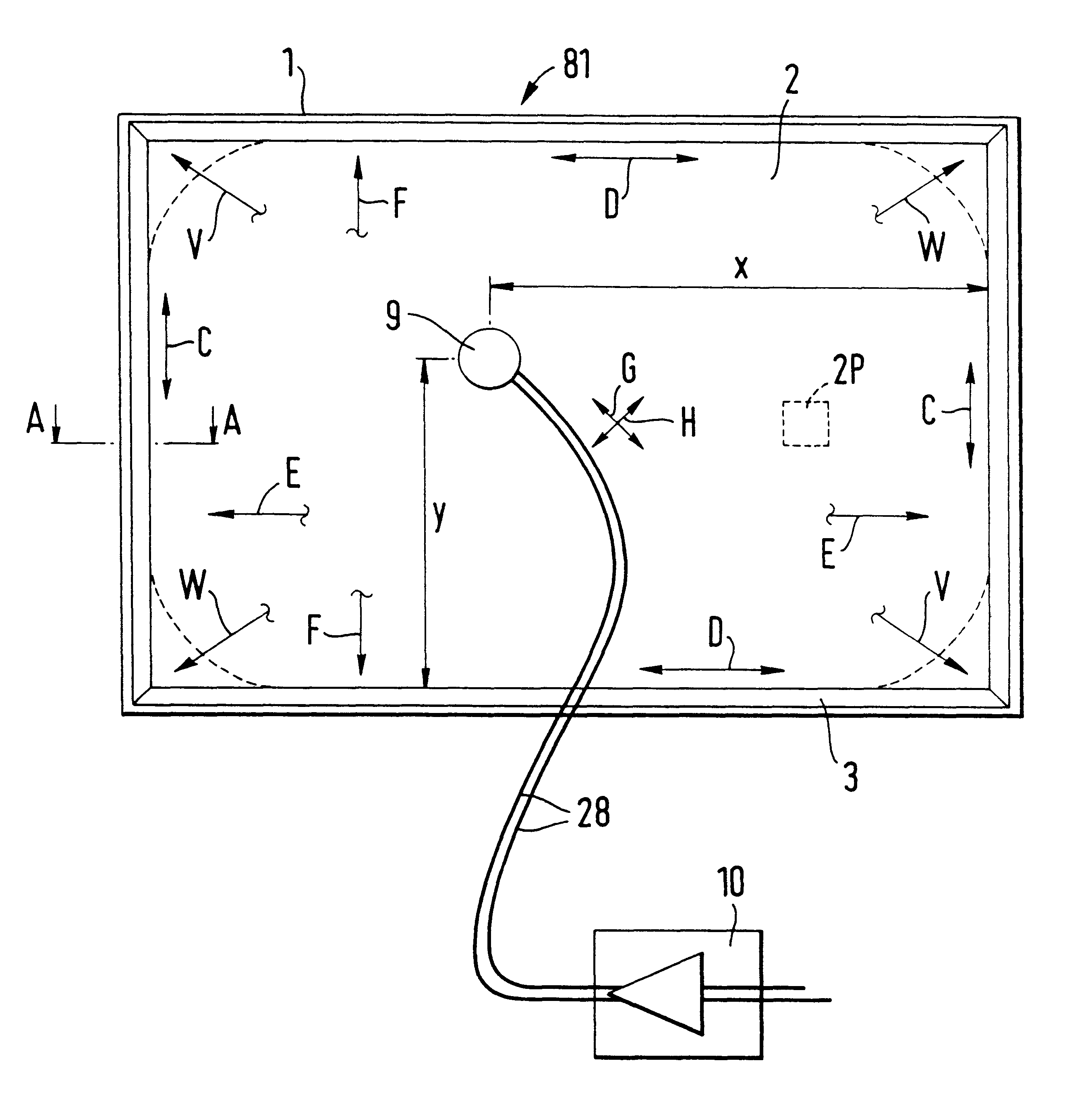
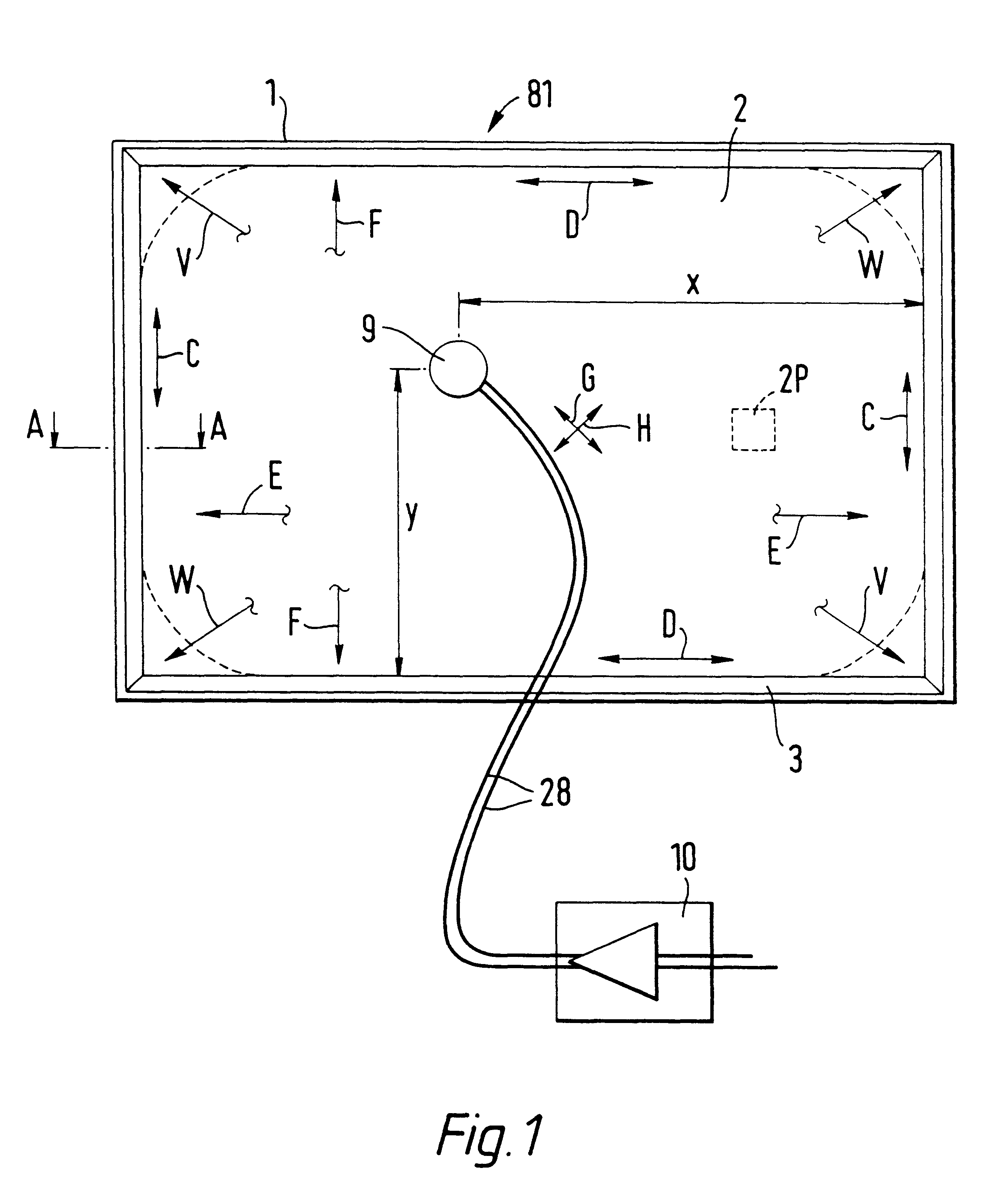
Referring to FIG. 1 of the drawings, a panel-form loudspeaker (81) comprises a rectangular frame (1) carrying a resilient suspension (3) round its inner periphery which supports a distributed mode sound radiating panel (2) formed structurally and configured as variously developed above. A transducer (9), e.g. as described later with reference to FIGS. 9-17, is mounted wholly and exclusively on or in the panel (2) at a predetermined location define by dimensions x and y. The latter are, of course the proportionate side length coordinates (from any corner) as indicated above. Conversion to being centre-related coordinates could be of general value, e.g. where corners of the panel member (2) are trimmed or cropped or finished short as made, see dashed (2d) and above regarding refinement of acoustic action / performance. Alternative, or combiningly and cooperatingly, effectively analogous such refinement by prescribing diagonal bending stiffness is also indicated diagrammatically, see arr...


PUM

PropertyMeasurementUnit
Areaaaaaaaaaaa
Areaaaaaaaaaaa
Areaaaaaaaaaaa

Abstract

Acoustic device including a member extending transversely of its thickness and capable of sustaining bending waves at least over an intendedly consequentially acoustically active area of the transverse extent of said member, the member having, by reason of orderly design methodology disclosed and claimed, a distribution of resonant modes of its natural bending wave vibration at least over said area that is dependent on values of particular parameters of said members, including geometrical configuration and directional bending stiffness(es), which values have been selected to predetermine said distribution of natural resonant modes being consonant with required achievable acoustic action of said member for operation of said device over a desired operative acoustic frequency range.

Description

The invention relates to acoustic devices for use in or as loudspeakers when driven or excited, usually by electrical signals via electrodynamic means; or in or as microphones when driven by incident acoustic energy, usually to produce a corresponding electrical signal; or in or for other acoustic devices or purposes.United Kingdom Patent applications as follows: No. 95 / 17918 filed Sep. 2nd 1995 for "Acoustic Device" No. 95 / 22281 filed Oct. 31st 1995 for "Acoustic Device" No. 96 / 06836 filed Mar. 30th 1996 for "Acoustic Device" from which priority is claimed are hereby incorporated by reference, in their entirety, into this application.GENERAL BACKGROUNDConventional loudspeakers in widespread use employ acoustic air-driving elements of so-called "cone" type. The or each cone element is mechanically driven at its smaller end in a pistonic manner, normally by a moving coil of electromagnetic means having an operatively associated fixed magnet assembly mounted to a frame or chassis of t...

Claims


Application Information

Patent Timeline
IPC IPC(8): B42D15/02G06F1/16G06F9/02G07F9/02H04R5/02H04R7/06H04R7/08H04R7/00H04R7/04H04R1/02H04R1/28H04R17/00B60R11/02H04N5/64H04R1/00H04R1/20H04R1/24H04R1/26H04R3/04H04R3/14H04R5/027H04R7/10H04R7/12H04R7/20H04R7/22H04R9/00H04R9/02H04R9/04H04R9/06H04R25/00H04R31/00
CPCB42D15/022G06F1/1601G06F1/1605G06F1/1616G06F1/1624G06F1/1688G06F9/02G07F9/02H04R1/021H04R1/025H04R1/028H04R1/24H04R1/26H04R1/2811H04R3/04H04R5/02H04R7/045H04R7/06H04R7/08H04R9/025H04R9/045H04R9/066H04R17/00G10H1/32H04R7/10H04R7/20H04R31/003B60R11/0217Y10T29/49005H04R1/2834H04R5/027H04R2201/021H04R2307/029H04R2440/07H04R2499/13H04R2499/15H04N5/642H04R3/14H04R7/12H04R2205/024H04R2307/201H04R2400/07H04R2440/03H04R2440/05H04R2499/11
Inventor AZIMA, HENRY FIROUZCOLLOMS, MARTINHARRIS, NEIL JOHN
Owner NEW TRANSDUCERS LTD
Why Eureka
Try Eureka