CMP polish pad and CMP processing apparatus using the same

a technology of polishing pad and processing apparatus, which is applied in the direction of gear teeth, gear teeth, gear machine, etc., can solve the problems of not necessarily providing advantages at all times, more complex and larger production apparatus

Inactive Publication Date: 2001-12-25
ROHM CO LTD
View PDF12 Cites 63 Cited by
  • Summary
  • Abstract
  • Description
  • Claims
  • Application Information

AI Technical Summary

Problems solved by technology

Although this constitution has such an advantage that the surface of the work can be polished uniformly, it may not necessarily provide adva...

Method used


Image

  • CMP polish pad and CMP processing apparatus using the same
  • CMP polish pad and CMP processing apparatus using the same
  • CMP polish pad and CMP processing apparatus using the same

Examples


third embodiment

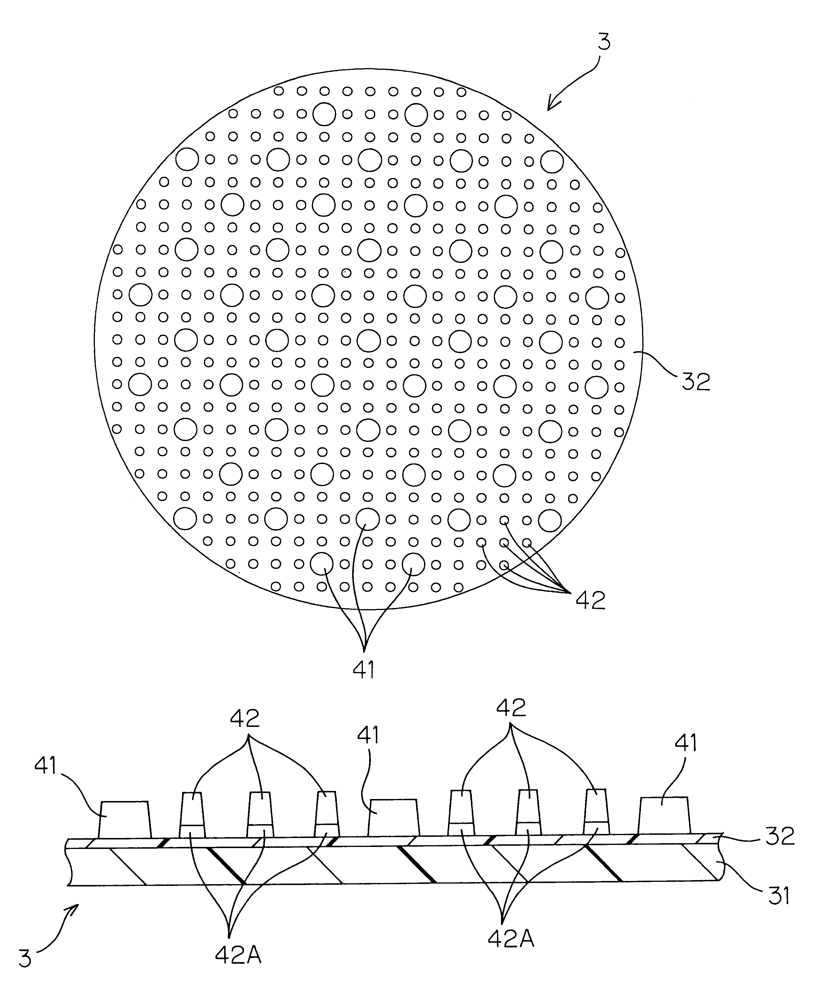
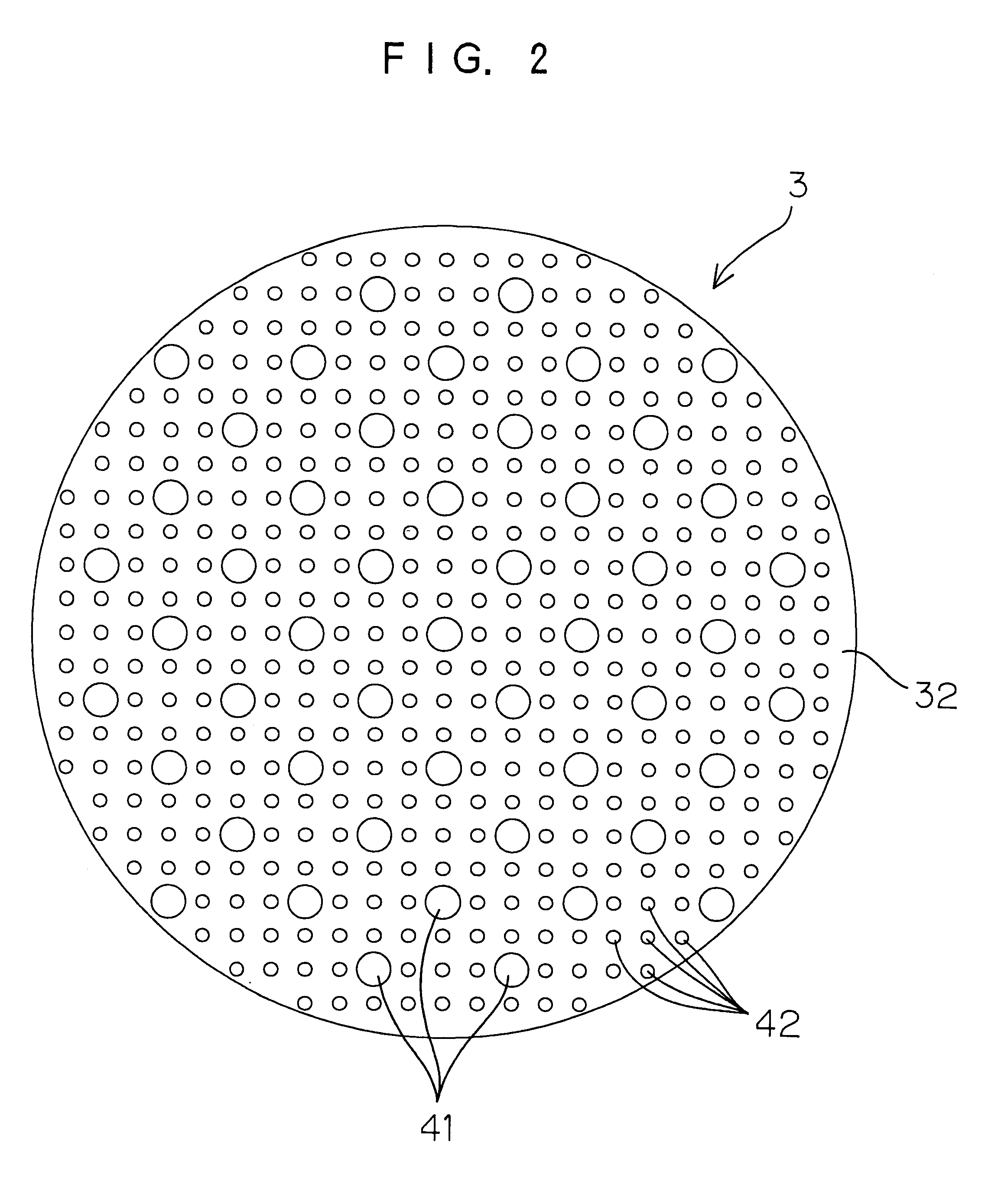
FIG. 11 is a plan view showing the constitution of the CMP polish pad according to the present invention. In FIG. 11, components that correspond to those of FIG. 2 and FIG. 3 will be denoted with the same reference numerals as those in FIG. 2 and FIG. 3. A polishing pad 70 has substantially disk shape, and has a plurality of first polishing portions 71A, 71B and 71C for rough polishing disposed in a concentric arrangement with the center thereof corresponding to the center of the disk. Disposed at positions offset from the first polishing portions 71A, 71B and 71C are second polishing portions 72 for fine polish uniformly distributed over the pad surface.

FIG. 12 is a partially enlarged sectional view in the radial direction of the polish pad 70. The first polishing portions 71A, 71B and 71C are formed so that sections perpendicular to the pad surface have substantially trapezoidal shape, and top surfaces 71a constitute concentric annular surfaces.

first embodiment

The second polishing portions 72 each has a shape of substantially truncated cone, and has elastic bodies 72A and abrasive particles 72B similarly to the case of the second polishing region 42 of the polishing pad 3 described above.

The polish pad 70 is used instead of the polish pad 3 of the constitution shown in FIG. 1. In this case, since the polish table 2 makes oscillating movement to trace a small circle in the horizontal plane instead of rotation, the ring-shaped first polishing regions 71A, 71B and 71C constantly change the position of contact with the wafer W in the radial direction of the wafer W.

In the case of the polish pad 70 of the constitution described above, too, increasing the force of pressing the wafer W against the polish pad 70 compresses the elastic bodies 72A of the second polishing portions 72 so that both the first polishing portions 71A, 71B and 71C and the second polishing portions 72 can make contact with the wafer W, thereby performing rough polish of t...


PUM

PropertyMeasurementUnit
Shapeaaaaaaaaaa
Areaaaaaaaaaaa
Heightaaaaaaaaaa

Abstract

A CMP polish pad used to chemically and mechanically polish a work to be polished. The CMP polish pad has polishing portions of two or more types, that have different conditions of contact with the work, provided on the pad surface. For example, polishing portions of a plurality of types having different coefficients of elasticity with respect to compression in the direction of pressing against the work may be provided on the pad surface. Also polishing portions of a plurality of types having different areas of contact with the work may be provided on the pad surface. Further, polishing portions of a plurality of types having different heights above the pad surface may be provided on the pad surface.

Description

1. Field of the InventionThe present invention relates to a CMP (Chemical Mechanical Polishing) pad used in chemically and mechanically polishing a work such as a semiconductor substrate (wafer), and a CMP processing apparatus using the same.2. Description of Related ArtIn a process of producing semiconductor devices, such a treatment is carried out that makes a wafer surface flat and smooth as required. The chemical and mechanical polishing (CMP) process has come to be regarded as a promising process for making a wafer surface smooth and flat.A CMP processing apparatus comprises a polish head that rotates while holding a wafer, a polish pad disposed to face the polish head, a platen that holds the polish pad, and a slurry supply unit that supplies a polishing medium (slurry) including a chemical liquid and abrasive particles (made of alumina, for example) onto the polish pad. With this constitution, when a wafer is pressed against the polish pad while rotating the polish head, the ...

Claims


Application Information

Patent Timeline
IPC IPC(8): B24D7/00B24D7/14B24B37/04B24B37/20B24B37/22B24B37/24H01L21/304
CPCB24B37/26B24D7/14
Inventor SUZUKI, KEISUKE
Owner ROHM CO LTD
Why Eureka
Try Eureka